Experience ultra-responsive pulse generation with LTC6993-2 and PIC18F47K42TQFP
“One-shot” pulse generator

Published Feb 13, 2024
Click board™
One Shot Click
Dev Board
Curiosity Nano with PIC18F47K42
Compiler
NECTO Studio
MCU
PIC18F47K42TQFP
Create accurately timed pulses, and ensure synchronized operations in various systems and devices
A
A
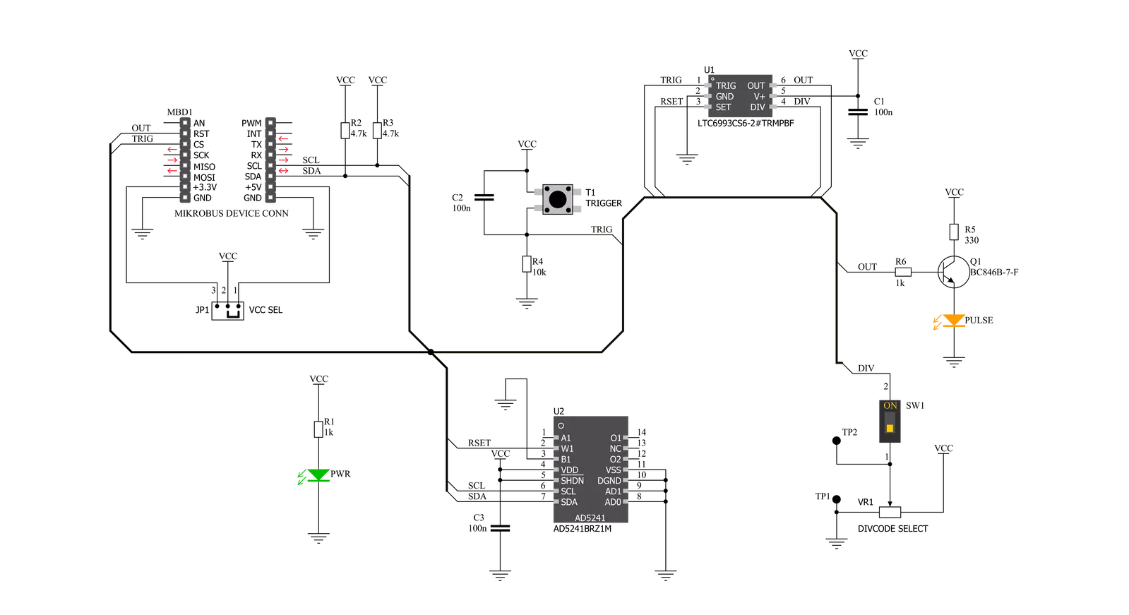
Hardware Overview
How does it work?
One Shot Click is based on the LTC6993-2, a monostable multivibrator (also known as a "one-shot" pulse generator) with a programmable pulse width of 1μs to 33.6 seconds from Analog Devices. The LTC6993-2 is part of the TimerBlox® family of versatile silicon timing devices. A single resistor, RSET, programs an internal master oscillator frequency, setting the LTC6993's time base. The output pulse width is determined by this master oscillator and an internal clock divider, NDIV, programmable to eight settings from 1 to 221. The output pulse is initiated by a transition on the trigger input (TRIG). Each part can be configured to generate positive or negative output pulses. The LTC6993-2 has four versions to provide different trigger signal polarity and retrigger capability. Besides that, LTC6993-2 also offers the ability to dynamically adjust the width of the output pulse via a separate control voltage brought to the SET
pin of the IC. A simple trimmer or potentiometer could be used; however, due to reliability reasons, the AD5241 digital potentiometer is used for that purpose on One Shot Click. The word is also about a 256-position digital potentiometer with a low-temperature coefficient (30 ppm/°C) from Analog Devices. The AD5241 communicates with the microcontroller over the standard I2C interface so that the user can easily control and precisely calculate the output pulse width just by simply setting the wiper value in the AD5241 registers. One Shot Click also contains the multi-turn trimmer wired as a resistor divider between V+ and GND and brought to the DIV pin of the LTC6993-2. The DIV pin is the programmable divider and polarity input. The polarity input, which pin voltage is internally converted into a 4-bit result (DIVCODE). The MSB of DIVCODE (POL) determines the polarity of the OUT pins. When
POL = 0, the output produces a positive pulse. When POL = 1, the output produces a negative pulse. That way, the user can easily set the output pulse width range, and polarity by setting the desired voltage on the trimmer mentioned (VR1). This Click also contains test points to ease the user's access to the referent voltage. One can separate the trimmer from the rest of the circuit using the separation switch (SW1), then precisely set and measure the desired voltage and turn the switch back in the ON position. This Click board™ can operate with either 3.3V or 5V logic voltage levels selected via the VCC SEL jumper. This way, both 3.3V and 5V capable MCUs can use the communication lines properly. Also, this Click board™ comes equipped with a library containing easy-to-use functions and an example code that can be used, as a reference, for further development.

Features overview
Development board
PIC18F47K42 Curiosity Nano evaluation kit is a cutting-edge hardware platform designed to evaluate the PIC18F47K42 microcontroller (MCU). Central to its design is the inclusion of the powerful PIC18F47K42 microcontroller (MCU), offering advanced functionalities and robust performance. Key features of this evaluation kit include a yellow user LED and a responsive mechanical user switch
providing seamless interaction and testing. The provision for a 32.768kHz crystal footprint ensures precision timing capabilities. With an onboard debugger boasting a green power and status LED, programming and debugging become intuitive and efficient. Further enhancing its utility is the Virtual serial port (CDC) and a debug GPIO channel (DGI GPIO), offering extensive connectivity options.
Powered via USB, this kit boasts an adjustable target voltage feature facilitated by the MIC5353 LDO regulator, ensuring stable operation with an output voltage ranging from 2.3V to 5.1V (limited by USB input voltage), with a maximum output current of 500mA, subject to ambient temperature and voltage constraints.

Microcontroller Overview
MCU Card / MCU

Architecture
PIC
MCU Memory (KB)
128
Silicon Vendor
Microchip
Pin count
40
RAM (Bytes)
8192
You complete me!
Accessories
Curiosity Nano Base for Click boards is a versatile hardware extension platform created to streamline the integration between Curiosity Nano kits and extension boards, tailored explicitly for the mikroBUS™-standardized Click boards and Xplained Pro extension boards. This innovative base board (shield) offers seamless connectivity and expansion possibilities, simplifying experimentation and development. Key features include USB power compatibility from the Curiosity Nano kit, alongside an alternative external power input option for enhanced flexibility. The onboard Li-Ion/LiPo charger and management circuit ensure smooth operation for battery-powered applications, simplifying usage and management. Moreover, the base incorporates a fixed 3.3V PSU dedicated to target and mikroBUS™ power rails, alongside a fixed 5.0V boost converter catering to 5V power rails of mikroBUS™ sockets, providing stable power delivery for various connected devices.

Used MCU Pins
mikroBUS™ mapper
Take a closer look
Schematic
Step by step
Project assembly

Start by selecting your development board and Click board™. Begin with the Curiosity Nano with PIC18F47K42 as your development board.


Track your results in real time
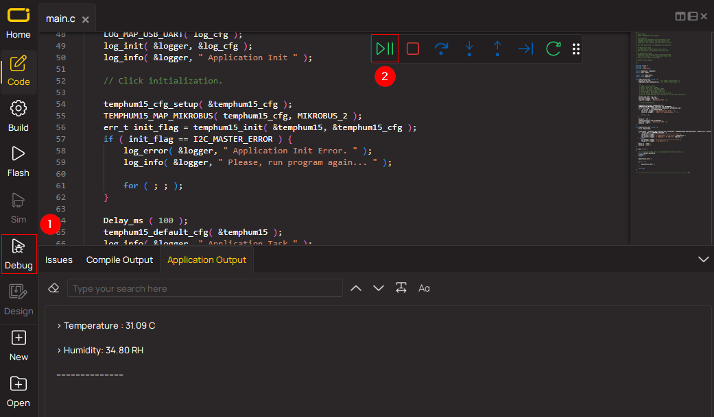
Application Output via Debug Mode
1. Once the code example is loaded, pressing the "DEBUG" button initiates the build process, programs it on the created setup, and enters Debug mode.
2. After the programming is completed, a header with buttons for various actions within the IDE becomes visible. Clicking the green "PLAY" button starts reading the results achieved with the Click board™. The achieved results are displayed in the Application Output tab.
Software Support
Library Description
This library contains API for One Shot Click driver.
Key functions:
oneshot_get_resistance- This function reads the resistance data from the AD5241 chiponeshot_digital_read_rst- This function reads the digital signal from the RST pinoneshot_digital_write_cs- This function writes the specified digital signal to the CS pin
Open Source
Code example
This example can be found in NECTO Studio. Feel free to download the code, or you can copy the code below.
/*!
 * \file
 * \brief OneShot Click example
 *
 * # Description
 * This example shows the user how to configure and use the One Shot click. The click has a
 * monostable monovibrator which cam generate a pulse of width between 1μs and 33.6 seconds.
 *
 * The demo application is composed of two sections :
 *
 * ## Application Init
 * This function initializes and configures the logger and click modules. Resistance data,
 * acquired from the AD5241, is displayed at the end of the initialization process.
 *
 * ## Application Task
 * This function triggers one shot every 8 seconds.
 *
 * \author MikroE Team
 *
 */
// ------------------------------------------------------------------- INCLUDES

#include "board.h"
#include "log.h"
#include "oneshot.h"

// ------------------------------------------------------------------ VARIABLES

static oneshot_t oneshot;
static log_t logger;

// ------------------------------------------------------ APPLICATION FUNCTIONS

void application_init ( )
{
    log_cfg_t log_cfg;
    oneshot_cfg_t cfg;

    /**
     * Logger initialization.
     * Default baud rate: 115200
     * Default log level: LOG_LEVEL_DEBUG
     * @note If USB_UART_RX and USB_UART_TX
     * are defined as HAL_PIN_NC, you will
     * need to define them manually for log to work.
     * See @b LOG_MAP_USB_UART macro definition for detailed explanation.
     */
    LOG_MAP_USB_UART( log_cfg );
    log_init( &logger, &log_cfg );
    log_info( &logger, "---- Application Init ----" );

    //  Click initialization.

    oneshot_cfg_setup( &cfg );
    ONESHOT_MAP_MIKROBUS( cfg, MIKROBUS_1 );
    oneshot_init( &oneshot, &cfg );
    Delay_100ms( );
    oneshot_default_cfg( &oneshot );
    Delay_100ms( );
    log_printf( &logger, " * Resistance: %.1f Ohm\r\n", oneshot_get_resistance( &oneshot ) );
}

void application_task ( )
{
    oneshot_digital_write_cs( &oneshot, 1 );
    Delay_ms( 1 );
    oneshot_digital_write_cs( &oneshot, 0 );
    log_printf( &logger, " * One shot triggered \r\n" );
    log_printf( &logger, " --------------------------- \r\n" );
    Delay_ms( 8000 );
}

void main ( )
{
    application_init( );

    for ( ; ; )
    {
        application_task( );
    }
}

// ------------------------------------------------------------------------ END


