Make every moment matter with ISL1221 and TM4C129ENCPDT
Counting the moments

Published Oct 21, 2023
Click board™
RTC 14 Click
Dev. board
Fusion for Tiva v8
Compiler
NECTO Studio
MCU
TM4C129ENCPDT
Take advantage of this cutting-edge real-time clock technology to achieve precise timing synchronization in your applications
A
A
Hardware Overview
How does it work?
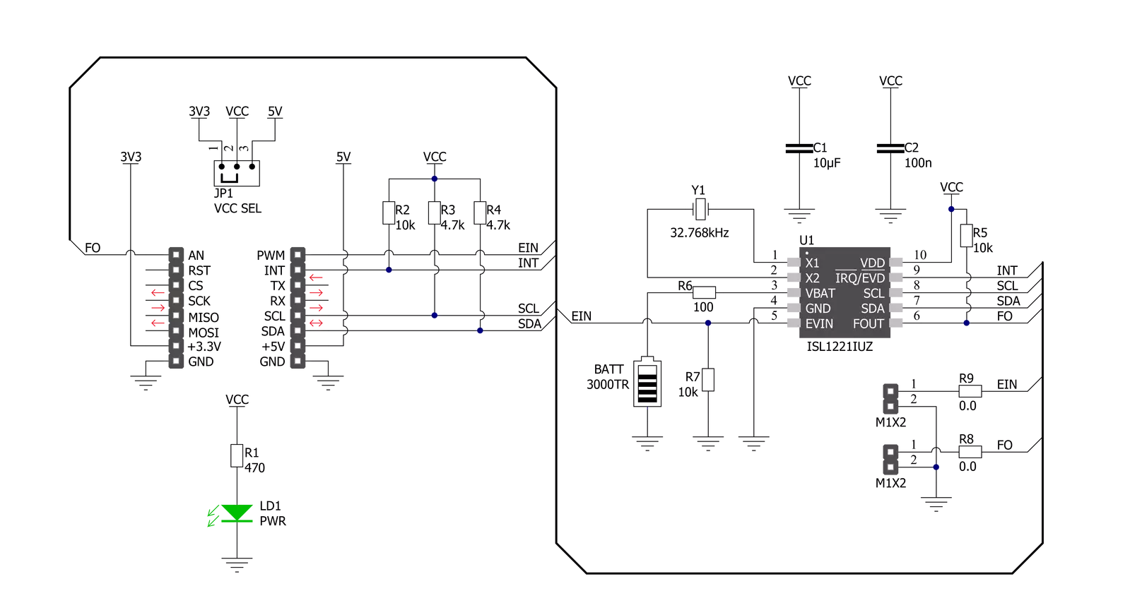
RTC 14 Click is based on the ISL1221, a small micropower real-time clock that provides increased security features and tamper detection from Renesas. This device has time-stamp features in normal and battery modes, timing and crystal compensation, clock/calendar, power fail indicator, periodic or polled alarm, intelligent battery backup switching, and battery-backed user SRAM. With their enhanced security functionality, this RTC is ideally suited for various applications ranging from security, warranty monitoring, data collection, recording, and time-stamping single events, for example, recurring events such as the opening and closing of a security door. As mentioned before, the ISL1221 can time-stamp an external event by either issuing an output signal containing the second, minute, hour, date, month, and year that the triggering event occurred or by stopping the RTC registers from advancing at the moment the event occurs. The device also has
calendar registers for a date, month, year, and day of the week, which is exceptionally accurate through 2099, with automatic leap year correction. The alarm can be set to any clock/calendar value (for example, every minute, every Friday, or at 9:41 AM on September 10). The alarm status is available by checking the Status Register or at the hardware interrupt pin routed to the INT pin of the mikroBUS™ socket. The alarm also contains a repeat mode, allowing a periodic interrupt every minute, every hour, and every day. RTC 14 Click communicates with MCU using the standard I2C 2-Wire interface to read data and configure settings, supporting a Fast Mode operation up to 400kHz. Also, it has a frequency output programmable from 32.768kHz to 1/32Hz, available at the PWM pin of the mikroBUS™ socket and onboard header pin labeled as FO. This feature is used for various timing applications, including clocking the MCU in sleep mode, eliminating
external crystal, and further reducing the BOM. To use features such as external event input or frequency output available on onboard headers, it is necessary to populate the resistors R8 and R9 and thus activate these functions on the headers. Like this one, the most common RTC configuration is a battery-backed up, which maintains time and may hold data in 2 bytes of battery-backed SRAM provided for data storage. That’s why, besides the ISL1221, the RTC 14 Click has a button cell battery holder compatible with the 3000TR battery holder, suitable for 12mm Coin Cell batteries. This Click board™ can operate with either 3.3V or 5V logic voltage levels selected via the VCC SEL jumper. This way, both 3.3V and 5V capable MCUs can use the communication lines properly. Also, this Click board™ comes equipped with a library containing easy-to-use functions and an example code that can be used as a reference for further development.

Features overview
Development board
Fusion for TIVA v8 is a development board specially designed for the needs of rapid development of embedded applications. It supports a wide range of microcontrollers, such as different 32-bit ARM® Cortex®-M based MCUs from Texas Instruments, regardless of their number of pins, and a broad set of unique functions, such as the first-ever embedded debugger/programmer over a WiFi network. The development board is well organized and designed so that the end-user has all the necessary elements, such as switches, buttons, indicators, connectors, and others, in one place. Thanks to innovative manufacturing technology, Fusion for TIVA v8 provides a fluid and immersive working experience, allowing access
anywhere and under any circumstances at any time. Each part of the Fusion for TIVA v8 development board contains the components necessary for the most efficient operation of the same board. An advanced integrated CODEGRIP programmer/debugger module offers many valuable programming/debugging options, including support for JTAG, SWD, and SWO Trace (Single Wire Output)), and seamless integration with the Mikroe software environment. Besides, it also includes a clean and regulated power supply module for the development board. It can use a wide range of external power sources, including a battery, an external 12V power supply, and a power source via the USB Type-C (USB-C) connector.
Communication options such as USB-UART, USB HOST/DEVICE, CAN (on the MCU card, if supported), and Ethernet is also included. In addition, it also has the well-established mikroBUS™ standard, a standardized socket for the MCU card (SiBRAIN standard), and two display options for the TFT board line of products and character-based LCD. Fusion for TIVA v8 is an integral part of the Mikroe ecosystem for rapid development. Natively supported by Mikroe software tools, it covers many aspects of prototyping and development thanks to a considerable number of different Click boards™ (over a thousand boards), the number of which is growing every day.

Microcontroller Overview
MCU Card / MCU

Type
8th Generation
Architecture
ARM Cortex-M4
MCU Memory (KB)
1024
Silicon Vendor
Texas Instruments
Pin count
128
RAM (Bytes)
262144
Used MCU Pins
mikroBUS™ mapper
Take a closer look
Click board™ Schematic
Step by step
Project assembly

Start by selecting your development board and Click board™. Begin with the Fusion for Tiva v8 as your development board.


Software Support
Library Description
This library contains API for RTC 14 Click driver.
Key functions:
rtc14_get_time- RTC 14 get time functionrtc14_set_time- RTC 14 set time functionrtc14_get_date- RTC 14 get date function
Open Source
Code example
The complete application code and a ready-to-use project are available through the NECTO Studio Package Manager for direct installation in the NECTO Studio. The application code can also be found on the MIKROE GitHub account.
/*!
 * @file main.c
 * @brief RTC14 Click example
 *
 * # Description
 * This is an example that demonstrates the use of the RTC 14 Click board™.
 *
 * The demo application is composed of two sections :
 *
 * ## Application Init
 * Initialization of I2C module, log UART and additional pins.
 * After driver initialization and default settings,
 * the app set the time to 11:59:50 PM ( 12-hour format )
 * and set date to Thursday 05.08.2021.
 *
 * ## Application Task
 * This is an example that shows the use of a RTC 14 Click board™.
 * In this example, we read and display the current time ( AM or PM )
 * and date ( day of the week ), which we also previously set.
 * Results are being sent to the Usart Terminal where you can track their changes.
 * All data logs write on USB changes every 1 sec.
 *
 * ## Additional Function
 * - static void display_day_of_week ( void ) - The function displays the day of the week.
 *
 * @author Nenad Filipovic
 *
 */

#include "board.h"
#include "log.h"
#include "rtc14.h"

static rtc14_t rtc14;
static log_t logger;
static uint8_t new_sec = 255;
static rtc14_time_t time;
static rtc14_date_t date;

static void display_day_of_week ( void )
{
    switch ( date.day_of_week )
    {
        case RTC14_DW_SUNDAY:
        {
            log_printf( &logger, "Su\r\n" );
            break;
        }
        case RTC14_DW_MONDAY:
        {
            log_printf( &logger, "Mo\r\n" );
            break;
        }
        case RTC14_DW_TUESDAY:
        {
            log_printf( &logger, "Tu\r\n" );
            break;
        }
        case RTC14_DW_WEDNESDAY:
        {
            log_printf( &logger, "We\r\n" );
            break;
        }
        case RTC14_DW_THURSDAY:
        {
            log_printf( &logger, "Th\r\n" );
            break;
        }
        case RTC14_DW_FRIDAY:
        {
            log_printf( &logger, "Fr\r\n" );
            break;
        }
        case RTC14_DW_SATURDAY:
        {
            log_printf( &logger, "Sa\r\n" );
            break;
        }
    }
}

void application_init ( void )
{
    log_cfg_t log_cfg;      /**< Logger config object. */
    rtc14_cfg_t rtc14_cfg;  /**< Click config object. */

    /**
     * Logger initialization.
     * Default baud rate: 115200
     * Default log level: LOG_LEVEL_DEBUG
     * @note If USB_UART_RX and USB_UART_TX
     * are defined as HAL_PIN_NC, you will
     * need to define them manually for log to work.
     * See @b LOG_MAP_USB_UART macro definition for detailed explanation.
     */
    LOG_MAP_USB_UART( log_cfg );
    log_init( &logger, &log_cfg );
    log_info( &logger, " Application Init " );

    // Click initialization.
    rtc14_cfg_setup( &rtc14_cfg );
    RTC14_MAP_MIKROBUS( rtc14_cfg, MIKROBUS_1 );
    err_t init_flag = rtc14_init( &rtc14, &rtc14_cfg );
    if ( I2C_MASTER_ERROR == init_flag )
    {
        log_error( &logger, " Application Init Error. " );
        log_info( &logger, " Please, run program again... " );

        for ( ; ; );
    }

    rtc14_default_cfg ( &rtc14 );
    Delay_ms ( 100 );

    time.hours_format = RTC14_SET_HOURS_FORMAT_12;
    time.am_pm = RTC14_SET_HOURS_FORMAT_12_PM;
    time.hours = 11;
    time.min = 59;
    time.sec = 50;
    rtc14_set_time( &rtc14, time );
    Delay_ms ( 100 );

    date.day_of_week = RTC14_DW_THURSDAY;
    date.day = 5;
    date.month = 8;
    date.year = 21;
    rtc14_set_date( &rtc14, date );
    Delay_ms ( 100 );

    log_info( &logger, " Application Task " );
    log_printf( &logger, "- - - - - - - - - - -\r\n" );
}

void application_task ( void )
{
    rtc14_get_time( &rtc14, &time );
    Delay_ms ( 1 );
    rtc14_get_date( &rtc14, &date );
    Delay_ms ( 1 );

    if ( time.sec != new_sec )
    {
        log_printf( &logger, "  Date : %.2d-%.2d-%.2d ", ( uint16_t ) date.day, ( uint16_t ) date.month, ( uint16_t ) date.year );
        display_day_of_week( );
        log_printf( &logger, "  Time : %.2d:%.2d:%.2d ", ( uint16_t ) time.hours, ( uint16_t ) time.min, ( uint16_t ) time.sec );
        log_printf( &logger, "%cM\r\n", ( time.am_pm == RTC14_SET_HOURS_FORMAT_12_PM ? 'P' : 'A' ) );
        log_printf( &logger, "- - - - - - - - - - -\r\n" );
        new_sec = time.sec;
        Delay_ms ( 1 );
    }
}

int main ( void )
{
    /* Do not remove this line or clock might not be set correctly. */
    #ifdef PREINIT_SUPPORTED
    preinit();
    #endif

    application_init( );

    for ( ; ; )
    {
        application_task( );
    }

    return 0;
}

// ------------------------------------------------------------------------ END


