Empower creativity and transform ideas into stunning visuals using IS31FL3731 and ATmega328P
Green LED wonderland: 16x9 magic in every pixel
Published Feb 14, 2024
Click board™
16x9 G Click
Dev. board
Arduino UNO Rev3
Compiler
NECTO Studio
MCU
ATmega328P
Simplify your visual communication needs with a solution that seamlessly integrates a 16x9 green LED matrix, allowing you to convey your messages and ideas precisely and excellently
A
A
Hardware Overview
How does it work?
16x9 G Click is based on the IS31FL3731, a LED array driver from ISSI. This device uses the cross-plexing technology which allows it to drive a large number of LED segments (144) with a small number of I/O pins. The IC has 28 pins in total, but it has two matrices with only 9 pins each for LED driving - which makes it 18 pins in total. It is possible by using the cross-plexing technique, also known as the Charlie-plexing, named by Charlie Allen, an engineer from Maxim Integrated, who made the first practical application example by utilizing this technique, for the company he was working at. The working principle of this technique is based around using Hi-Z pins. This adds the third element for the LED control, unlike the commonly used matrix multiplexing, when two pins can change states to either LOW-HI or HI-LOW, saving only a single pin per cell. A basic cell of the cross-plexed LED matrix consists of three pins and 6 LEDs which is substantially more than the regular matrix. The bigger the matrix is, the higher the efficiency of such multiplexing becomes. N pins are able to drive N2-N LED segments. The IS31FL3731 has some additional features. Besides two banks of driving pins, it can store up to 8 frames in its internal memory. This allows small movies to be autonomously played back by the IC itself, without using the MCU processing power. The device can operate in Picture Mode, in the Auto Frame Mode, and in the Audio Frame Mode. While operating in Picture mode, it will display a
selected frame and can apply a breathing effect to it. Auto Frame Mode will sequence through all the frames. The delay between frames, as well as the transition effect, can be configured by the user. The Auto Frame Mode can also be used as the buffer for playing back more frames, which can be externally loaded to the IC while it plays back its 8 frames buffer. Finally, the Audio Frame Mode allows the audio signal at the IN pin to control the frame rate advancement (lowest signal level will display the first frame, the highest signal level will display the last frame). All the programmable parameters are stored via the I2C to appropriate registers. The datasheet of the IS31FL3731 offers ian n-depth explanation of all the registers. The interrupt engine allows the interrupt event to be generated by pulling the INTB pin to a LOW logic level and setting the appropriate status register bit to 1. INTB pin will report whenever the cycle in the Auto Frame Mode is finished. Every time when the frame sequence is ended, this pin will be pulsed to a LOW logic level, and after 7ms, it will return to a HIGH logic level, automatically. The INT bit signalizing the interrupt will be cleared once the Status Register is read by the host MCU but will not automatically revert to 0. The INTB pin is routed to the mikroBUS™ INT pin. The SDB pin can be used to completely turn off the IC when power saving is a concern. Pulling this pin to a LOW logic level will put the device into the Hardware Shutdown Mode, which powers down
the entire IC. No read or write operations are possible, unlike the Software Shutdown Mode, which is set by a bit in the respective (Shutdown) register. Software shutdown Mode will turn off the drivers and most of the IC, but the communication will be possible. In fact, some registers can be read only in Software Shutdown Mode, such as the Frame registers. The SDB pin is normally pulled to a LOW logic level by the onboard pulldown resistor, so initialization procedure should contain setting this pin to a HIGH logic level. The SDB pin routed to the mikroBUS™ CS pin and it is labeled as SDB. The IN pin of the IS31FL3731 is used to sample the input data and either modulate the LED segment brightness according or advance the playback frame. It is decoupled by a capacitor, accepting the line-level audio signal. On the 16x9 Click board™, this pin is routed to the PWM pin of the mikroBUS™, thus the PWM signal from the MCU can be used instead of the audio signal. Naturally, the device will still react to an audio source, since the PWM signal is just another type of a waveform applied to the IN pin. The PWM pin of the mikroBUS™ is labeled as IN on the Click board™. There are two SMD jumpers on this Click board™. The first SMD jumper is used to select the least significant bit (LSB) of the I2C address, and it is labeled as the ADDR SEL. The second SMD jumper is labeled as the VCC SEL and it is used to set the operating voltage of the device, allowing it to be interfaced with both 3.3V and 5V MCUs.


Features overview
Development board
Arduino UNO is a versatile microcontroller board built around the ATmega328P chip. It offers extensive connectivity options for various projects, featuring 14 digital input/output pins, six of which are PWM-capable, along with six analog inputs. Its core components include a 16MHz ceramic resonator, a USB connection, a power jack, an
ICSP header, and a reset button, providing everything necessary to power and program the board. The Uno is ready to go, whether connected to a computer via USB or powered by an AC-to-DC adapter or battery. As the first USB Arduino board, it serves as the benchmark for the Arduino platform, with "Uno" symbolizing its status as the
first in a series. This name choice, meaning "one" in Italian, commemorates the launch of Arduino Software (IDE) 1.0. Initially introduced alongside version 1.0 of the Arduino Software (IDE), the Uno has since become the foundational model for subsequent Arduino releases, embodying the platform's evolution.

Microcontroller Overview
MCU Card / MCU

Architecture
AVR
MCU Memory (KB)
32
Silicon Vendor
Microchip
Pin count
28
RAM (Bytes)
2048
You complete me!
Accessories
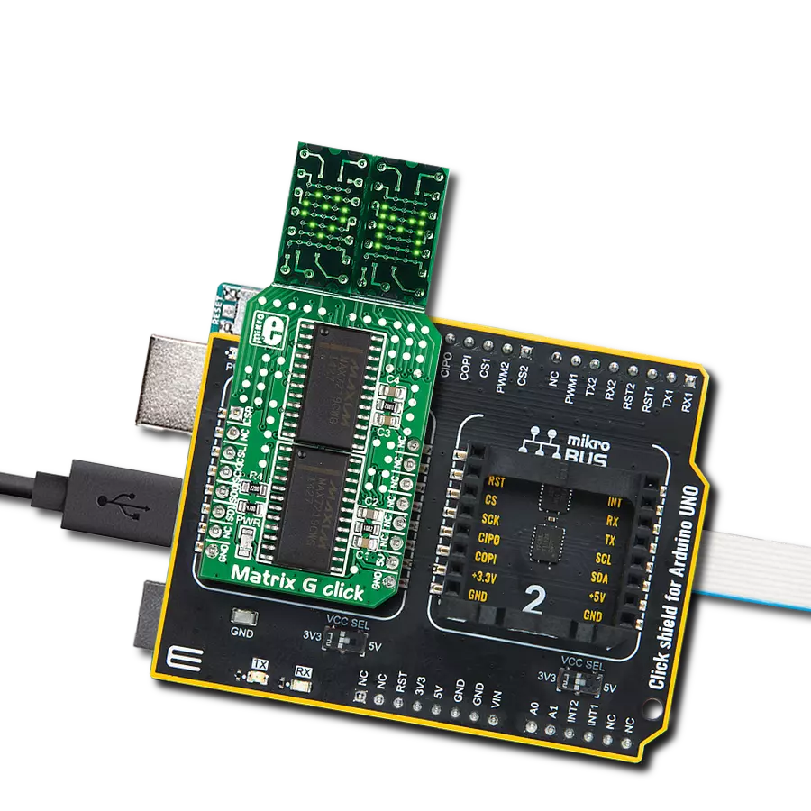
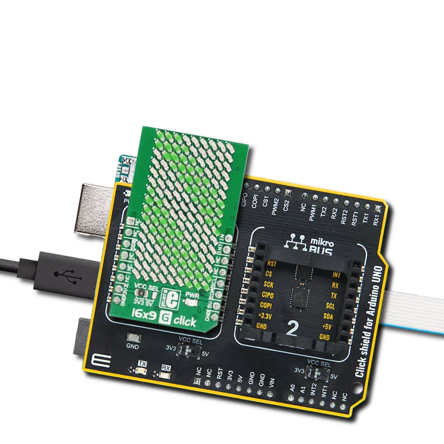
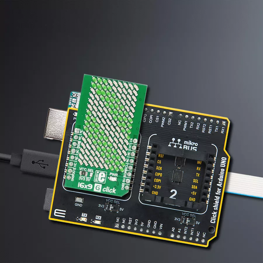
Click Shield for Arduino UNO has two proprietary mikroBUS™ sockets, allowing all the Click board™ devices to be interfaced with the Arduino UNO board without effort. The Arduino Uno, a microcontroller board based on the ATmega328P, provides an affordable and flexible way for users to try out new concepts and build prototypes with the ATmega328P microcontroller from various combinations of performance, power consumption, and features. The Arduino Uno has 14 digital input/output pins (of which six can be used as PWM outputs), six analog inputs, a 16 MHz ceramic resonator (CSTCE16M0V53-R0), a USB connection, a power jack, an ICSP header, and reset button. Most of the ATmega328P microcontroller pins are brought to the IO pins on the left and right edge of the board, which are then connected to two existing mikroBUS™ sockets. This Click Shield also has several switches that perform functions such as selecting the logic levels of analog signals on mikroBUS™ sockets and selecting logic voltage levels of the mikroBUS™ sockets themselves. Besides, the user is offered the possibility of using any Click board™ with the help of existing bidirectional level-shifting voltage translators, regardless of whether the Click board™ operates at a 3.3V or 5V logic voltage level. Once you connect the Arduino UNO board with our Click Shield for Arduino UNO, you can access hundreds of Click boards™, working with 3.3V or 5V logic voltage levels.

Used MCU Pins
mikroBUS™ mapper
Take a closer look
Click board™ Schematic

Step by step
Project assembly

Start by selecting your development board and Click board™. Begin with the Arduino UNO Rev3 as your development board.


Track your results in real time
Application Output
1. Application Output - In Debug mode, the 'Application Output' window enables real-time data monitoring, offering direct insight into execution results. Ensure proper data display by configuring the environment correctly using the provided tutorial.

2. UART Terminal - Use the UART Terminal to monitor data transmission via a USB to UART converter, allowing direct communication between the Click board™ and your development system. Configure the baud rate and other serial settings according to your project's requirements to ensure proper functionality. For step-by-step setup instructions, refer to the provided tutorial.

3. Plot Output - The Plot feature offers a powerful way to visualize real-time sensor data, enabling trend analysis, debugging, and comparison of multiple data points. To set it up correctly, follow the provided tutorial, which includes a step-by-step example of using the Plot feature to display Click board™ readings. To use the Plot feature in your code, use the function: plot(*insert_graph_name*, variable_name);. This is a general format, and it is up to the user to replace 'insert_graph_name' with the actual graph name and 'variable_name' with the parameter to be displayed.

Software Support
Library Description
This library contains API for 16x9 G Click driver.
Key functions:
c16x9_draw_rectangle- Draw rectanglec16x9_display_image- Image display functionc16x9_draw_point- Functions for draw point.
Open Source
Code example
The complete application code and a ready-to-use project are available through the NECTO Studio Package Manager for direct installation in the NECTO Studio. The application code can also be found on the MIKROE GitHub account.
/*!
 * \file
 * \brief 16x9 Click example
 *
 * # Description
 * Demo application is used to shows basic controls 16x9 Click
 *
 * The demo application is composed of two sections :
 *
 * ## Application Init
 * Configuring Clicks and log objects.
 * Set basic images and characters to be drawn on the screen.
 *
 * ## Application Task
 * Display character, image and rectangle every 1 second.
 *
 * \author Katarina Perendic
 *
 */
// ------------------------------------------------------------------- INCLUDES

#include "board.h"
#include "log.h"
#include "c16x9.h"

// ------------------------------------------------------------------ VARIABLES

static c16x9_t c16x9;
static log_t logger;

c16x9_image_t image_on;
c16x9_image_t image_off;
c16x9_char_t  data_char;
c16x9_rectangle_t rectangle;

// ------------------------------------------------------ APPLICATION FUNCTIONS

void application_init ( void )
{
    log_cfg_t log_cfg;
    c16x9_cfg_t cfg;

    /**
     * Logger initialization.
     * Default baud rate: 115200
     * Default log level: LOG_LEVEL_DEBUG
     * @note If USB_UART_RX and USB_UART_TX
     * are defined as HAL_PIN_NC, you will
     * need to define them manually for log to work.
     * See @b LOG_MAP_USB_UART macro definition for detailed explanation.
     */
    LOG_MAP_USB_UART( log_cfg );
    log_init( &logger, &log_cfg );
    log_info( &logger, "---- Application Init ----" );

    //  Click initialization.

    c16x9_cfg_setup( &cfg );
    C16X9_MAP_MIKROBUS( cfg, MIKROBUS_1 );
    c16x9_init( &c16x9, &cfg );

    // Image ON

    image_on.buf[ 0 ] = 0x0000;
    image_on.buf[ 1 ] = 0xC630;
    image_on.buf[ 2 ] = 0x6318;
    image_on.buf[ 3 ] = 0x318C;
    image_on.buf[ 4 ] = 0x18C6;
    image_on.buf[ 5 ] = 0x318C;
    image_on.buf[ 6 ] = 0x6318;
    image_on.buf[ 7 ] = 0xC630;
    image_on.buf[ 8 ] = 0x0000;

    image_on.frame = C16X9_FRAME_1;
    image_on.pwm = 250;

    // Image OFF

    image_off.buf[ 0 ] = 0xFFFF;
    image_off.buf[ 1 ] = 0x39CF;
    image_off.buf[ 2 ] = 0x9CE7;
    image_off.buf[ 3 ] = 0xCE73;
    image_off.buf[ 4 ] = 0xE739;
    image_off.buf[ 5 ] = 0xCE73;
    image_off.buf[ 6 ] = 0x9CE7;
    image_off.buf[ 7 ] = 0x39CF;
    image_off.buf[ 8 ] = 0xFFFF;

    image_off.frame = C16X9_FRAME_1;
    image_off.pwm = 250;

    // Char

    data_char.character = 'G';
    data_char.frame = C16X9_FRAME_1;
    data_char.pwm = 250;

    // Rectangle

    rectangle.x = 1;
    rectangle.y = 4;
    rectangle.width = 6;
    rectangle.height = 4;
    rectangle.frame = C16X9_FRAME_1;
    rectangle.pwm = 250;
}

void application_task ( void )
{
    //  Task implementation.

    c16x9_display_refresh( &c16x9 );
    c16x9_display_byte( &c16x9, &data_char );
    Delay_ms ( 1000 );
    Delay_ms ( 1000 );

    c16x9_display_refresh( &c16x9 );
    c16x9_display_image( &c16x9, &image_on );
    Delay_ms ( 1000 );
    Delay_ms ( 1000 );

    c16x9_display_refresh( &c16x9 );
    c16x9_display_image( &c16x9, &image_off );
    Delay_ms ( 1000 );
    Delay_ms ( 1000 );

    c16x9_display_refresh( &c16x9 );
    c16x9_draw_rectangle( &c16x9, &rectangle );
    Delay_ms ( 1000 );
    Delay_ms ( 1000 );
}

int main ( void )
{
    /* Do not remove this line or clock might not be set correctly. */
    #ifdef PREINIT_SUPPORTED
    preinit();
    #endif

    application_init( );

    for ( ; ; )
    {
        application_task( );
    }

    return 0;
}


// ------------------------------------------------------------------------ END
Additional Support
Resources
Category:LED Matrix