From 3D to 6DoF with IIM-42652 and ATmega328P
Simplify motion analysis and control
Published Feb 14, 2024
Click board™
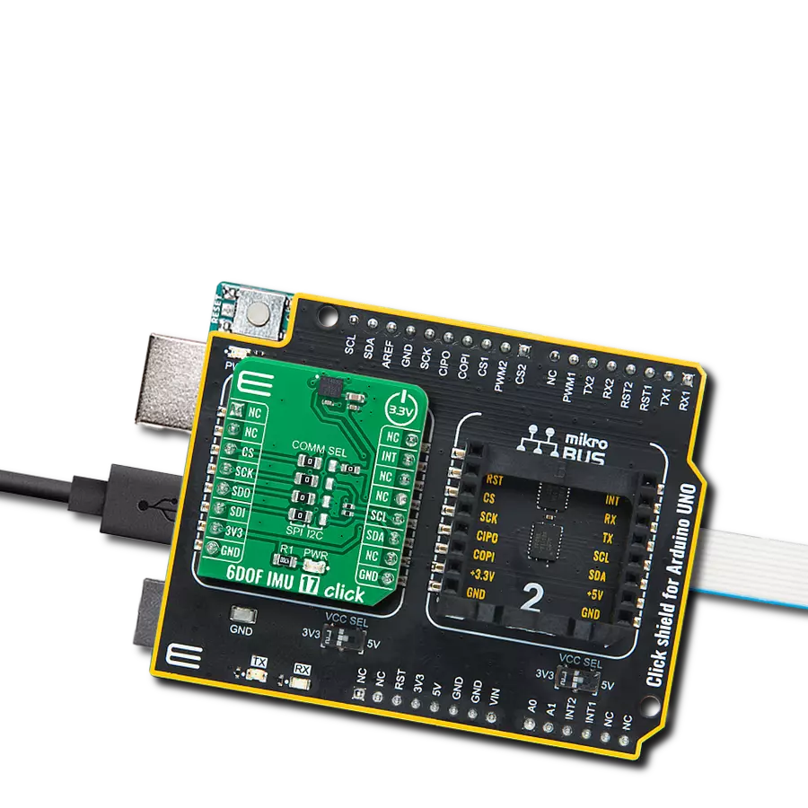
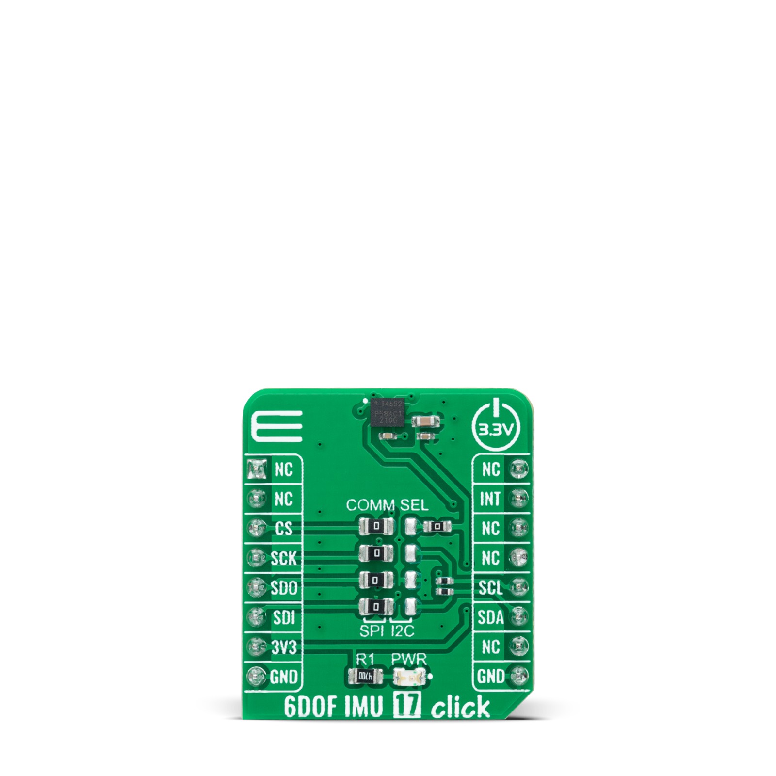
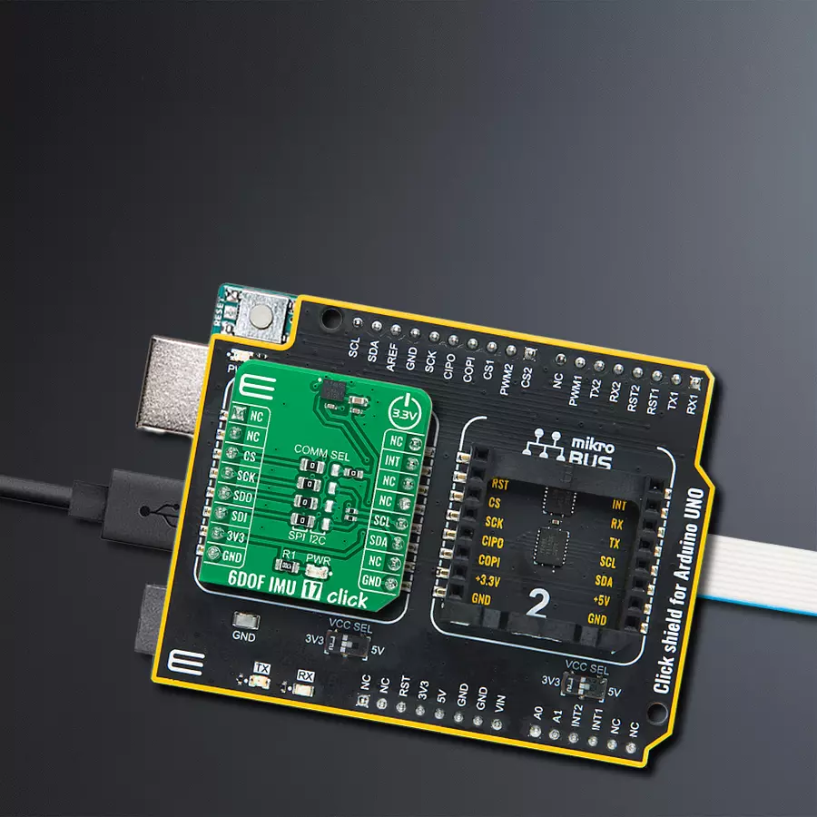
6DOF IMU 17 Click
Dev. board
Arduino UNO Rev3
Compiler
NECTO Studio
MCU
ATmega328P
Our 6-axis motion tracking solution is engineered to provide precise monitoring of movement and orientation, empowering industries with valuable data for various applications
A
A
Hardware Overview
How does it work?
6DOF IMU 17 Click is based on the IIM-42652, a 6-axis motion tracking device that combines a 3-axis gyroscope and a 3-axis accelerometer from TDK InvenSense. It features a 2K-byte FIFO that can lower the traffic on the selected serial bus interface and reduce power consumption by allowing the system processor to burst read sensor data and then go into a low-power mode. With its 6-axis integration, the IIM-42652 guarantees optimal motion performance for customers. The IIM-42652 supports an extended operating temperature range, allowing customers to design it into various industrial IoT applications, including navigation and stabilizing industrial machinery and robots. The gyroscope supports eight programmable full-scale range settings from
±15.625dps to ±2000dps, and the accelerometer supports four programmable full-scale range settings from ±2g to ±16g. Other industry-leading features include on-chip 16-bit ADCs, programmable digital filters, an embedded temperature sensor, and programmable interrupts. The IIM-42652 also provides high robustness by supporting 20,000g shock reliability. 6DOF IMU 17 Click provides the possibility of using both I2C and SPI interfaces with a maximum frequency of 1MHz for I2C and 24MHz for SPI communication. The selection can be made by positioning SMD jumpers labeled as COMM SEL in an appropriate position. Note that all the jumpers' positions must be on the same side, or the Click board™ may become unresponsive. Interrupt
functionality is configured via the Interrupt Configuration register, which allows for interrupt pin configuration routed to the INT pin of the mikroBUS™ socket (used to signal MCU that an event has been sensed), the interrupt latching and clearing method, and triggers for the interrupt. The interrupt status can be read from the Interrupt Status register. This Click board™ can be operated only with a 3.3V logic voltage level. The board must perform appropriate logic voltage level conversion before using MCUs with different logic levels. Also, it comes equipped with a library containing functions and an example code that can be used as a reference for further development.
Features overview
Development board
Arduino UNO is a versatile microcontroller board built around the ATmega328P chip. It offers extensive connectivity options for various projects, featuring 14 digital input/output pins, six of which are PWM-capable, along with six analog inputs. Its core components include a 16MHz ceramic resonator, a USB connection, a power jack, an
ICSP header, and a reset button, providing everything necessary to power and program the board. The Uno is ready to go, whether connected to a computer via USB or powered by an AC-to-DC adapter or battery. As the first USB Arduino board, it serves as the benchmark for the Arduino platform, with "Uno" symbolizing its status as the
first in a series. This name choice, meaning "one" in Italian, commemorates the launch of Arduino Software (IDE) 1.0. Initially introduced alongside version 1.0 of the Arduino Software (IDE), the Uno has since become the foundational model for subsequent Arduino releases, embodying the platform's evolution.

Microcontroller Overview
MCU Card / MCU

Architecture
AVR
MCU Memory (KB)
32
Silicon Vendor
Microchip
Pin count
28
RAM (Bytes)
2048
You complete me!
Accessories
Click Shield for Arduino UNO has two proprietary mikroBUS™ sockets, allowing all the Click board™ devices to be interfaced with the Arduino UNO board without effort. The Arduino Uno, a microcontroller board based on the ATmega328P, provides an affordable and flexible way for users to try out new concepts and build prototypes with the ATmega328P microcontroller from various combinations of performance, power consumption, and features. The Arduino Uno has 14 digital input/output pins (of which six can be used as PWM outputs), six analog inputs, a 16 MHz ceramic resonator (CSTCE16M0V53-R0), a USB connection, a power jack, an ICSP header, and reset button. Most of the ATmega328P microcontroller pins are brought to the IO pins on the left and right edge of the board, which are then connected to two existing mikroBUS™ sockets. This Click Shield also has several switches that perform functions such as selecting the logic levels of analog signals on mikroBUS™ sockets and selecting logic voltage levels of the mikroBUS™ sockets themselves. Besides, the user is offered the possibility of using any Click board™ with the help of existing bidirectional level-shifting voltage translators, regardless of whether the Click board™ operates at a 3.3V or 5V logic voltage level. Once you connect the Arduino UNO board with our Click Shield for Arduino UNO, you can access hundreds of Click boards™, working with 3.3V or 5V logic voltage levels.

Used MCU Pins
mikroBUS™ mapper
Take a closer look
Click board™ Schematic

Step by step
Project assembly

Start by selecting your development board and Click board™. Begin with the Arduino UNO Rev3 as your development board.


Track your results in real time
Application Output
1. Application Output - In Debug mode, the 'Application Output' window enables real-time data monitoring, offering direct insight into execution results. Ensure proper data display by configuring the environment correctly using the provided tutorial.

2. UART Terminal - Use the UART Terminal to monitor data transmission via a USB to UART converter, allowing direct communication between the Click board™ and your development system. Configure the baud rate and other serial settings according to your project's requirements to ensure proper functionality. For step-by-step setup instructions, refer to the provided tutorial.

3. Plot Output - The Plot feature offers a powerful way to visualize real-time sensor data, enabling trend analysis, debugging, and comparison of multiple data points. To set it up correctly, follow the provided tutorial, which includes a step-by-step example of using the Plot feature to display Click board™ readings. To use the Plot feature in your code, use the function: plot(*insert_graph_name*, variable_name);. This is a general format, and it is up to the user to replace 'insert_graph_name' with the actual graph name and 'variable_name' with the parameter to be displayed.

Software Support
Library Description
This library contains API for 6DOF IMU 17 Click driver.
Key functions:
c6dofimu17_get_accel_data- 6DOF IMU 17 get accel data functionc6dofimu17_get_gyro_data- 6DOF IMU 17 get gyroscope data functionc6dofimu17_get_temperature- 6DOF IMU 17 get temperature data function.
Open Source
Code example
The complete application code and a ready-to-use project are available through the NECTO Studio Package Manager for direct installation in the NECTO Studio. The application code can also be found on the MIKROE GitHub account.
/*!
 * @file main.c
 * @brief 6DOFIMU17 Click example
 *
 * # Description
 * This library contains API for 6DOF IMU 17 Click driver.
 * The library initializes and defines the I2C or SPI bus drivers
 * to write and read data from registers.
 * The library also includes a function for reading
 * accelerometer and gyroscope X-axis, Y-axis, and Z-axis data
 * as well as the temperature in degrees Celsius.
 *
 * The demo application is composed of two sections :
 *
 * ## Application Init
 * The initialization of I2C or SPI module, log UART, and additional pins.
 * After the driver init, the app checks communication,
 * sensor ID, and then executes a default configuration.
 *
 * ## Application Task
 * This is an example that shows the use of a 6DOF IMU 17 Click board™.
 * Measures and displays acceleration and gyroscope data for X-axis, Y-axis, and Z-axis
 * and the temperature in degrees Celsius.
 * Results are being sent to the USART terminal where the user can track their changes.
 * This task repeats every 100 ms.
 *
 * @author Nenad Filipovic
 *
 */

#include "board.h"
#include "log.h"
#include "c6dofimu17.h"

static c6dofimu17_t c6dofimu17;
static log_t logger;

void application_init ( void )
{
    log_cfg_t log_cfg;                /**< Logger config object. */
    c6dofimu17_cfg_t c6dofimu17_cfg;  /**< Click config object. */
    uint8_t device_id;

    /**
     * Logger initialization.
     * Default baud rate: 115200
     * Default log level: LOG_LEVEL_DEBUG
     * @note If USB_UART_RX and USB_UART_TX
     * are defined as HAL_PIN_NC, you will
     * need to define them manually for log to work.
     * See @b LOG_MAP_USB_UART macro definition for detailed explanation.
     */
    LOG_MAP_USB_UART( log_cfg );
    log_init( &logger, &log_cfg );
    log_info( &logger, " Application Init " );

    // Click initialization.
    c6dofimu17_cfg_setup( &c6dofimu17_cfg );
    C6DOFIMU17_MAP_MIKROBUS( c6dofimu17_cfg, MIKROBUS_1 );
    err_t init_flag  = c6dofimu17_init( &c6dofimu17, &c6dofimu17_cfg );
    if ( ( I2C_MASTER_ERROR == init_flag ) || ( SPI_MASTER_ERROR == init_flag ) )
    {
        log_error( &logger, " Application Init Error. " );
        log_info( &logger, " Please, run program again... " );

       for ( ; ; );
    }

    c6dofimu17_default_cfg ( &c6dofimu17 );
    Delay_ms ( 100 );

    c6dofimu17_get_device_id( &c6dofimu17, &device_id );
    Delay_ms ( 100 );
    if ( device_id == C6DOFIMU17_CHIP_ID )
    {
        log_printf( &logger, "\t\t  Communication OK\r\n" );
    }
    else
    {
        log_printf( &logger, "\t\tCommunication ERROR\r\n" );
        log_printf( &logger, "\t\t  Reset the device\r\n" );

        for ( ; ; );
    }

    log_printf( &logger, "\t--------------------------------------\r\n" );
    Delay_ms ( 100 );
}

void application_task ( void )
{
    c6dofimu17_axis_t accel_data;
    c6dofimu17_axis_t gyro_data;
    float temperature;
    if ( ( C6DOFIMU17_OK == c6dofimu17_get_accel_data( &c6dofimu17, &accel_data ) ) &&
         ( C6DOFIMU17_OK == c6dofimu17_get_gyro_data( &c6dofimu17, &gyro_data ) ) &&
         ( C6DOFIMU17_OK == c6dofimu17_get_temperature( &c6dofimu17, &temperature ) ) )
    {
        log_printf( &logger, "\t Accel X: %d\t|\tGyro X: %d\r\n", accel_data.x, gyro_data.x );
        log_printf( &logger, "\t Accel Y: %d\t|\tGyro Y: %d\r\n", accel_data.y, gyro_data.y );
        log_printf( &logger, "\t Accel Z: %d\t|\tGyro Z: %d\r\n", accel_data.z, gyro_data.z );
        log_printf( &logger, "\t- - - - - - - - - -  - - - - - - - - -\r\n" );
        log_printf( &logger, "\t\t Temperature: %.2f C\r\n", temperature );
        log_printf( &logger, "\t--------------------------------------\r\n" );
    }
    Delay_ms ( 100 );
}

int main ( void )
{
    /* Do not remove this line or clock might not be set correctly. */
    #ifdef PREINIT_SUPPORTED
    preinit();
    #endif

    application_init( );

    for ( ; ; )
    {
        application_task( );
    }

    return 0;
}

// ------------------------------------------------------------------------ END
Additional Support
Resources
Category:Motion


