Detect falls and impacts easily with MXC62320MP and ATmega328P
Making sense of motion: The magic of accelerometers
Published Feb 14, 2024
Click board™
Accel 17 Click
Dev. board
Arduino UNO Rev3
Compiler
NECTO Studio
MCU
ATmega328P
This solution is invaluable for measuring and analyzing changes in velocity and acceleration, providing essential data for a wide range of purposes
A
A
Hardware Overview
How does it work?
Accel 17 Click is based on the MXC62320MP, a complete dual-axis acceleration measurement system fabricated on a monolithic CMOS process from MEMSIC. The MXC62320MP operation is based on heat transfer by natural convection and operates like other accelerometers, except it is a gas in the MEMSIC sensor. It can measure dynamic acceleration (e.g., vibration) and static acceleration (e.g., gravity), with full-scale acceleration measurements ranging from ±2g. It also comes with embedded Power Up/Down and self-test function, resolution better than 1mg, and >50.000g shock survival rating. In addition to all
these features, it also has excellent temperature stability and low power consumption/low active current. This accelerometer can enter a Power-Down mode by writing a command [xxxxxxx1] into the accelerometer’s internal register, while a Wake-Up operation is performed when a command of [xxxxxxx0] is written into the same register. Note that the MXC62320MP needs about 75ms (typical) for Power-Up time. Accel 17 Click communicates with MCU using a standard I2C 2-Wire interface that supports 400kHz Fast Mode operation. Since the sensor for operation requires a 3.3V logic voltage level only, this Click board™
also features the PCA9306 voltage-level translator from Texas Instruments. The I2C interface bus lines are routed to the dual bidirectional voltage-level translator, allowing this Click board™ to work properly with both 3.3V and 5V MCUs. This Click board™ can operate with either 3.3V or 5V logic voltage levels selected via the VIO SEL jumper. This way, both 3.3V and 5V capable MCUs can use the communication lines properly. Also, this Click board™ comes equipped with a library containing easy-to-use functions and an example code that can be used as a reference for further development.


Features overview
Development board
Arduino UNO is a versatile microcontroller board built around the ATmega328P chip. It offers extensive connectivity options for various projects, featuring 14 digital input/output pins, six of which are PWM-capable, along with six analog inputs. Its core components include a 16MHz ceramic resonator, a USB connection, a power jack, an
ICSP header, and a reset button, providing everything necessary to power and program the board. The Uno is ready to go, whether connected to a computer via USB or powered by an AC-to-DC adapter or battery. As the first USB Arduino board, it serves as the benchmark for the Arduino platform, with "Uno" symbolizing its status as the
first in a series. This name choice, meaning "one" in Italian, commemorates the launch of Arduino Software (IDE) 1.0. Initially introduced alongside version 1.0 of the Arduino Software (IDE), the Uno has since become the foundational model for subsequent Arduino releases, embodying the platform's evolution.

Microcontroller Overview
MCU Card / MCU

Architecture
AVR
MCU Memory (KB)
32
Silicon Vendor
Microchip
Pin count
28
RAM (Bytes)
2048
You complete me!
Accessories
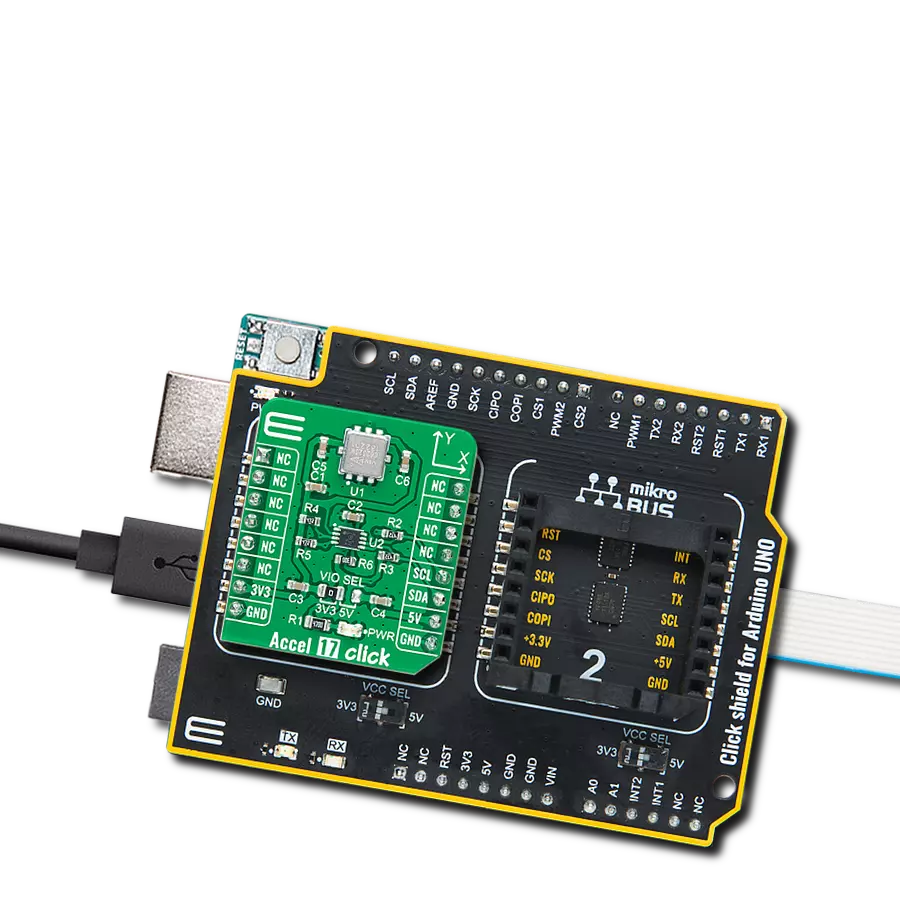
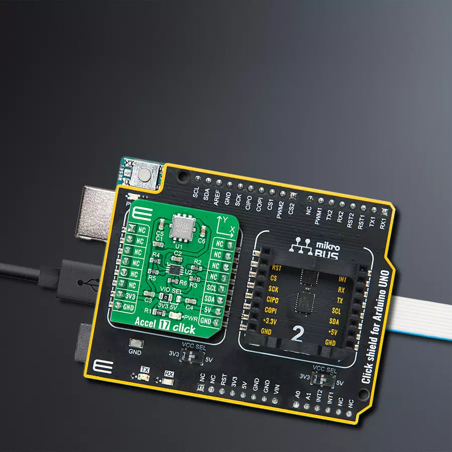
Click Shield for Arduino UNO has two proprietary mikroBUS™ sockets, allowing all the Click board™ devices to be interfaced with the Arduino UNO board without effort. The Arduino Uno, a microcontroller board based on the ATmega328P, provides an affordable and flexible way for users to try out new concepts and build prototypes with the ATmega328P microcontroller from various combinations of performance, power consumption, and features. The Arduino Uno has 14 digital input/output pins (of which six can be used as PWM outputs), six analog inputs, a 16 MHz ceramic resonator (CSTCE16M0V53-R0), a USB connection, a power jack, an ICSP header, and reset button. Most of the ATmega328P microcontroller pins are brought to the IO pins on the left and right edge of the board, which are then connected to two existing mikroBUS™ sockets. This Click Shield also has several switches that perform functions such as selecting the logic levels of analog signals on mikroBUS™ sockets and selecting logic voltage levels of the mikroBUS™ sockets themselves. Besides, the user is offered the possibility of using any Click board™ with the help of existing bidirectional level-shifting voltage translators, regardless of whether the Click board™ operates at a 3.3V or 5V logic voltage level. Once you connect the Arduino UNO board with our Click Shield for Arduino UNO, you can access hundreds of Click boards™, working with 3.3V or 5V logic voltage levels.

Used MCU Pins
mikroBUS™ mapper
Take a closer look
Click board™ Schematic

Step by step
Project assembly

Start by selecting your development board and Click board™. Begin with the Arduino UNO Rev3 as your development board.


Track your results in real time
Application Output
1. Application Output - In Debug mode, the 'Application Output' window enables real-time data monitoring, offering direct insight into execution results. Ensure proper data display by configuring the environment correctly using the provided tutorial.

2. UART Terminal - Use the UART Terminal to monitor data transmission via a USB to UART converter, allowing direct communication between the Click board™ and your development system. Configure the baud rate and other serial settings according to your project's requirements to ensure proper functionality. For step-by-step setup instructions, refer to the provided tutorial.

3. Plot Output - The Plot feature offers a powerful way to visualize real-time sensor data, enabling trend analysis, debugging, and comparison of multiple data points. To set it up correctly, follow the provided tutorial, which includes a step-by-step example of using the Plot feature to display Click board™ readings. To use the Plot feature in your code, use the function: plot(*insert_graph_name*, variable_name);. This is a general format, and it is up to the user to replace 'insert_graph_name' with the actual graph name and 'variable_name' with the parameter to be displayed.

Software Support
Library Description
This library contains API for Accel 17 Click driver.
Key functions:
accel17_get_axes_data- Accel data readingaccel17_generic_read- Reading functionaccel17_generic_write- Writing function
Open Source
Code example
The complete application code and a ready-to-use project are available through the NECTO Studio Package Manager for direct installation in the NECTO Studio. The application code can also be found on the MIKROE GitHub account.
/*!
 * @file main.c
 * @brief Accel17 Click example
 *
 * # Description
 * This example showcases ability of the device to read
 * x, y axis orientation.
 *
 * The demo application is composed of two sections :
 *
 * ## Application Init
 * Initialization of communication modules(I2C, UART), and
 * configures device.
 *
 * ## Application Task
 * Reads axis data and calculates it and logs result every 300ms.
 *
 * @author Luka Filipovic
 *
 */

#include "board.h"
#include "log.h"
#include "accel17.h"

static accel17_t accel17;
static log_t logger;

void application_init ( void )
{
    log_cfg_t log_cfg;  /**< Logger config object. */
    accel17_cfg_t accel17_cfg;  /**< Click config object. */

    /**
     * Logger initialization.
     * Default baud rate: 115200
     * Default log level: LOG_LEVEL_DEBUG
     * @note If USB_UART_RX and USB_UART_TX
     * are defined as HAL_PIN_NC, you will
     * need to define them manually for log to work.
     * See @b LOG_MAP_USB_UART macro definition for detailed explanation.
     */
    LOG_MAP_USB_UART( log_cfg );
    log_init( &logger, &log_cfg );
    log_info( &logger, " Application Init " );

    // Click initialization.
    accel17_cfg_setup( &accel17_cfg );
    ACCEL17_MAP_MIKROBUS( accel17_cfg, MIKROBUS_1 );
    err_t init_flag = accel17_init( &accel17, &accel17_cfg );
    if ( I2C_MASTER_ERROR == init_flag )
    {
        log_error( &logger, " Application Init Error. " );
        log_info( &logger, " Please, run program again... " );

        for ( ; ; );
    }

    accel17_default_cfg ( &accel17 );
    Delay_ms ( 1000 );
    log_info( &logger, " Application Task " );
}

void application_task ( void )
{
    accel17_axes_t axes;
    accel17_get_axes_data ( &accel17, &axes );
    log_printf( &logger, " > X[degree]: %.2f\r\n > Y[degree]: %.2f\r\n", axes.x, axes.y );
    log_printf( &logger, "*********************************\r\n" );
    Delay_ms ( 300 );
}

int main ( void )
{
    /* Do not remove this line or clock might not be set correctly. */
    #ifdef PREINIT_SUPPORTED
    preinit();
    #endif

    application_init( );

    for ( ; ; )
    {
        application_task( );
    }

    return 0;
}

// ------------------------------------------------------------------------ END
Additional Support
Resources
Category:Motion


