Measure vibration or acceleration of motion using BMA400 and ATmega328P
Unlocking motion's hidden potential
Published Feb 14, 2024
Click board™
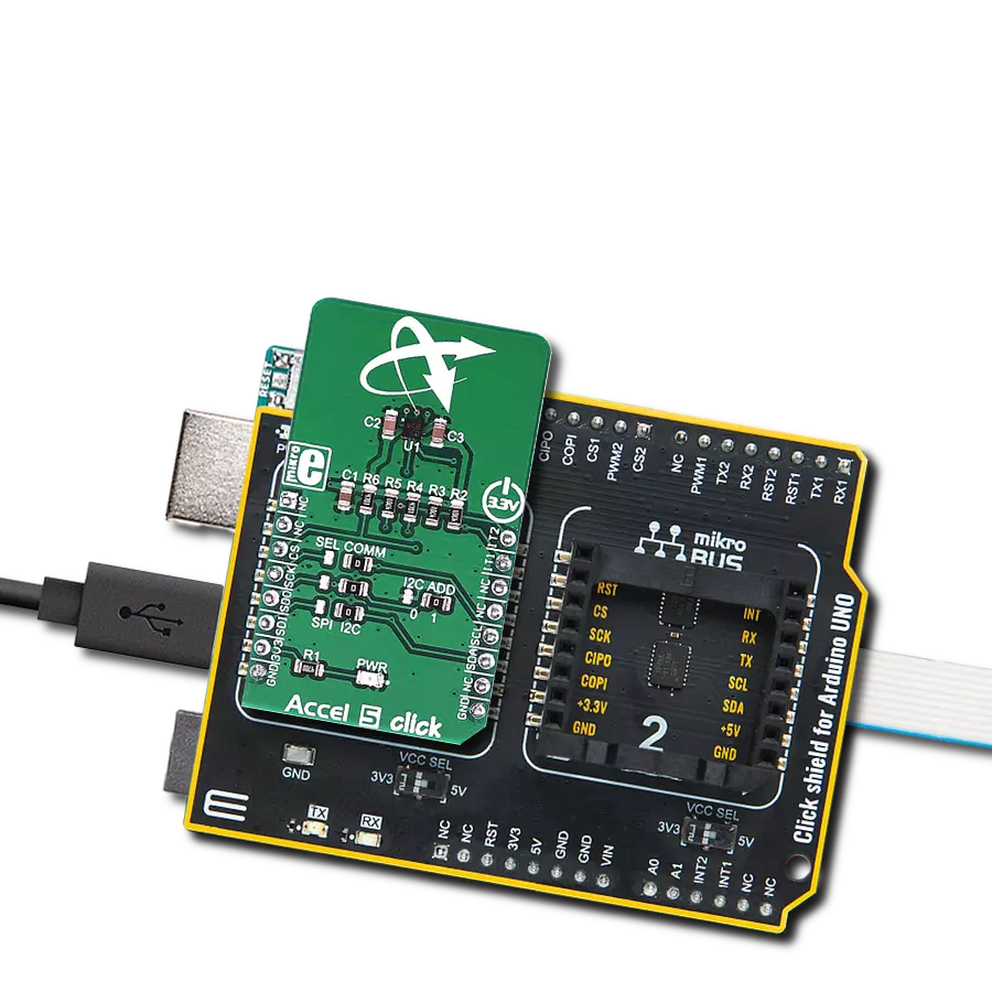
Accel 5 Click
Dev. board
Arduino UNO Rev3
Compiler
NECTO Studio
MCU
ATmega328P
Easily measure acceleration forces and enable the monitoring of motion and changes in velocity
A
A
Hardware Overview
How does it work?
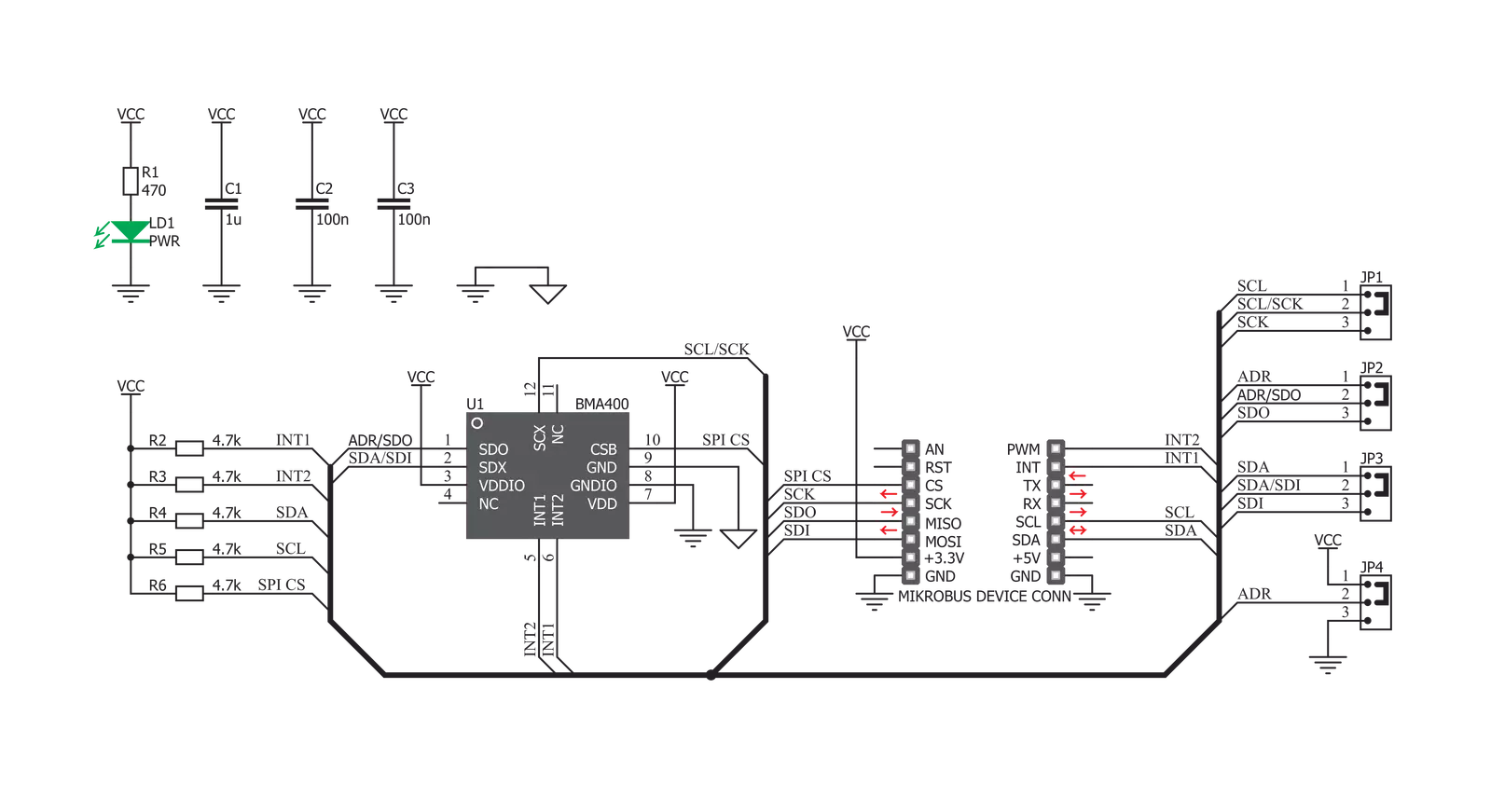
Accel 5 Click is based on the BMA400, an ultra-low power triaxial accelerometer sensor, from Bosch Sensortec. This sensor has many features perfectly suited for IoT applications and wearables, offering a good balance between the performance and the power consumption. One of its key features is its ultra-low power consumption, allowing it to be used in various always-on low power applications. To improve the battery life even more, this sensor also features a Sleep mode when the sensor current consumption is in magnitude of few hundred nanoamperes. This sensor can measure the acceleration in ranges of ±2 g, ±4 g, ±8, and ±16 g. It also offers lowpass filtering of the output data, in the range from 0.48 x ODR (Output Data Refresh rate), up to maximal ODR frequency of 800Hz. An internal 12bit A/D converter ensures reliable and low noise operation, so that the data coming from the internal MEMS remains clean and accurate. Three power modes allow customized balance between the power consumption and performance. An extensive integrated interrupt engine offers many distinctive functionalities, such as the automatic enter/exit Low Power mode, advanced actions detection such as the running, walking, several other features such as the step counting, and more. After the POR (Power ON Reset) event, the device stays in the Sleep mode. In Sleep mode, the sensor practically does not consume any power (about 300nA), but the sensor functionality is completely suspended. To use the sensor, it has to be either in Low Power mode, where it uses a fixed Output Data Refresh (ODR) of 25Hz, or in the Normal mode. Some options are exclusive only to Normal mode, such as the step counting detection,
output filtering and so on. Normal mode still uses power conservative, allowing the device to be used in the Always-ON low power applications. While operating in Normal mode, two filters are available for the data filtering. The filters can be applied either to the output registers, the FIFO engine, or can be used to process the interrupt data. The first filter can be used to obtain data rates from 12.5Hz up to 800Hz, which is defined by the filter registers, while the second filter offers fixed frequency of 100Hz, superimposed by a frequency of 1Hz. The output noise is affected by the ODR frequency. Acceleration data is available in 12-bit format from both the data registers and the internal FIFO buffer of 1kb. The FIFO buffer can be used for more complex calculations or timed readings. Writing to FIFO buffer is only allowed in the Normal mode, while it can be read in the Low power mode, too. The interrupt engine facilitates the complete FIFO buffer, triggering an interrupt for several FIFO events: overflow event, watermark event, almost full event, and so on. The BMA400 sensor contains an integrated timer, which can be used along with the interrupts to be used for the auto Wakeup or auto Power down functions. The automatic functions are a part of the sensor power management. The automatic mode changes can be set either to an acceleration interrupt after a specified threshold is reached, or it can be set to a timer interrupt: when the timer expires, the interrupt is generated, and the power mode is switched. An extensive interrupt engine offers two layers of interrupts. It offers basic interrupts, including some basic functions, such as the Data Ready interrupt, FIFO buffer related interrupts and the Wakeup event interrupt. Basic interrupts also
report Interrupt overrun event, where too many interrupts are competing, so that the sensor is not able to process them all. Besides the basic interrupts, the interrupt engine offers some more sophisticated, advanced interrupts, that include detection all of the activities: tap/double tap, step counting, activity changed, orientation changed, and two generic interrupts. The advanced interrupts require a certain ODR rate and can be used in the Normal mode exclusively, while basic interrupts offer more rudimental control over events. The advanced interrupt engine can use two programmable interrupt pins. Both of these pins can be assigned with any interrupt source and can be either LOW or HIGH on interrupt, depending on settings in appropriate registers. These two pins are routed to INT and PWM pins of the mikroBUS™, and are labeled as IT1 and IT2, respectively. Besides the acceleration MEMS and complementary analog front-end circuitry, the BMA400 sensor also has an integrated temperature sensor. It is updated every 160ms and sampled with the 8-bit resolution. Thermal data is always available, except when the device is in the Sleep mode. Accel 5 click offers two communication interfaces. It can be used with either I2C or SPI. The onboard SMD jumpers labeled as SEL COM allow switching between the two interfaces. Note that all the jumpers have to be positioned either to I2C or to SPI position. When I2C interface is selected, an additional SMD jumper labeled as the I2C ADD becomes available, determining the least significant bit of the BMA400 I2C address. The Click board™ should be interfaced only with MCUs that operate on 3.3V.


Features overview
Development board
Arduino UNO is a versatile microcontroller board built around the ATmega328P chip. It offers extensive connectivity options for various projects, featuring 14 digital input/output pins, six of which are PWM-capable, along with six analog inputs. Its core components include a 16MHz ceramic resonator, a USB connection, a power jack, an
ICSP header, and a reset button, providing everything necessary to power and program the board. The Uno is ready to go, whether connected to a computer via USB or powered by an AC-to-DC adapter or battery. As the first USB Arduino board, it serves as the benchmark for the Arduino platform, with "Uno" symbolizing its status as the
first in a series. This name choice, meaning "one" in Italian, commemorates the launch of Arduino Software (IDE) 1.0. Initially introduced alongside version 1.0 of the Arduino Software (IDE), the Uno has since become the foundational model for subsequent Arduino releases, embodying the platform's evolution.

Microcontroller Overview
MCU Card / MCU

Architecture
AVR
MCU Memory (KB)
32
Silicon Vendor
Microchip
Pin count
28
RAM (Bytes)
2048
You complete me!
Accessories
Click Shield for Arduino UNO has two proprietary mikroBUS™ sockets, allowing all the Click board™ devices to be interfaced with the Arduino UNO board without effort. The Arduino Uno, a microcontroller board based on the ATmega328P, provides an affordable and flexible way for users to try out new concepts and build prototypes with the ATmega328P microcontroller from various combinations of performance, power consumption, and features. The Arduino Uno has 14 digital input/output pins (of which six can be used as PWM outputs), six analog inputs, a 16 MHz ceramic resonator (CSTCE16M0V53-R0), a USB connection, a power jack, an ICSP header, and reset button. Most of the ATmega328P microcontroller pins are brought to the IO pins on the left and right edge of the board, which are then connected to two existing mikroBUS™ sockets. This Click Shield also has several switches that perform functions such as selecting the logic levels of analog signals on mikroBUS™ sockets and selecting logic voltage levels of the mikroBUS™ sockets themselves. Besides, the user is offered the possibility of using any Click board™ with the help of existing bidirectional level-shifting voltage translators, regardless of whether the Click board™ operates at a 3.3V or 5V logic voltage level. Once you connect the Arduino UNO board with our Click Shield for Arduino UNO, you can access hundreds of Click boards™, working with 3.3V or 5V logic voltage levels.

Used MCU Pins
mikroBUS™ mapper
Take a closer look
Click board™ Schematic
Step by step
Project assembly

Start by selecting your development board and Click board™. Begin with the Arduino UNO Rev3 as your development board.


Track your results in real time
Application Output
1. Application Output - In Debug mode, the 'Application Output' window enables real-time data monitoring, offering direct insight into execution results. Ensure proper data display by configuring the environment correctly using the provided tutorial.

2. UART Terminal - Use the UART Terminal to monitor data transmission via a USB to UART converter, allowing direct communication between the Click board™ and your development system. Configure the baud rate and other serial settings according to your project's requirements to ensure proper functionality. For step-by-step setup instructions, refer to the provided tutorial.

3. Plot Output - The Plot feature offers a powerful way to visualize real-time sensor data, enabling trend analysis, debugging, and comparison of multiple data points. To set it up correctly, follow the provided tutorial, which includes a step-by-step example of using the Plot feature to display Click board™ readings. To use the Plot feature in your code, use the function: plot(*insert_graph_name*, variable_name);. This is a general format, and it is up to the user to replace 'insert_graph_name' with the actual graph name and 'variable_name' with the parameter to be displayed.

Software Support
Library Description
This library contains API for Accel 5 Click driver.
Key functions:
accel5_write_byte- Functions for write one byte in registeraccel5_read_byte- Functions for read byte from registeraccel5_read_data- Functions for read data from register
Open Source
Code example
The complete application code and a ready-to-use project are available through the NECTO Studio Package Manager for direct installation in the NECTO Studio. The application code can also be found on the MIKROE GitHub account.
/*!
 * \file
 * \brief Accel5 Click example
 *
 * # Description
 * This application allows linear motion and gravitational force measurements.
 *
 * The demo application is composed of two sections :
 *
 * ## Application Init
 * Initializes Driver init and settings accelerometer data range and mode.
 *
 * ## Application Task
 * Reads the accel X / Y / Z axis data, every 500 ms.
 *
 * \author MikroE Team
 *
 */
// ------------------------------------------------------------------- INCLUDES

#include "board.h"
#include "log.h"
#include "accel5.h"

// ------------------------------------------------------------------ VARIABLES

static accel5_t accel5;
static log_t logger;

// ------------------------------------------------------ APPLICATION FUNCTIONS

void application_init ( void )
{
    log_cfg_t log_cfg;
    accel5_cfg_t cfg;

    /**
     * Logger initialization.
     * Default baud rate: 115200
     * Default log level: LOG_LEVEL_DEBUG
     * @note If USB_UART_RX and USB_UART_TX
     * are defined as HAL_PIN_NC, you will
     * need to define them manually for log to work.
     * See @b LOG_MAP_USB_UART macro definition for detailed explanation.
     */
    LOG_MAP_USB_UART( log_cfg );
    log_init( &logger, &log_cfg );
    log_info( &logger, "---- Application Init ----" );

    //  Click initialization.

    accel5_cfg_setup( &cfg );
    ACCEL5_MAP_MIKROBUS( cfg, MIKROBUS_1 );

    if ( accel5_init( &accel5, &cfg ) == ACCEL5_INIT_ERROR )
    {
        log_info( &logger, "---- Application Error ----" );

        for ( ; ; );
    }

    log_info( &logger, "---- Application Init Done ----\n" );

    accel5_soft_reset( &accel5 );
    Delay_ms ( 500 );
    accel5_default_cfg( &accel5, ACCEL5_CFG_0_NORMAL_MODE, ACCEL5_CFG_1_ACC_RANGE_4g );
    Delay_ms ( 500 );
}

void application_task ( void )
{
    int16_t x_axis_data;
    int16_t y_axis_data;
    int16_t z_axis_data;

    //  Task implementation.

    x_axis_data = accel5_get_axis( &accel5, ACCEL5_X_AXIS );
    log_printf ( &logger, " X axis : %d\r\n", x_axis_data );

    y_axis_data = accel5_get_axis( &accel5, ACCEL5_Y_AXIS );
    log_printf ( &logger, " Y axis : %d\r\n", y_axis_data );

    z_axis_data = accel5_get_axis( &accel5, ACCEL5_Z_AXIS );
    log_printf ( &logger, " Z axis : %d\r\n\n", z_axis_data );

    Delay_ms ( 500 );
}

int main ( void )
{
    /* Do not remove this line or clock might not be set correctly. */
    #ifdef PREINIT_SUPPORTED
    preinit();
    #endif

    application_init( );

    for ( ; ; )
    {
        application_task( );
    }

    return 0;
}

// ------------------------------------------------------------------------ END
Additional Support
Resources
Category:Motion


