Charge smarter not harder with the help of MCP73123 and ATmega328P
Stay powered, stay productive
Published Feb 14, 2024
Click board™
Charger 11 Click
Dev. board
Arduino UNO Rev3
Compiler
NECTO Studio
MCU
ATmega328P
Fast, safe, and reliable charging that never lets you down
A
A
Hardware Overview
How does it work?
Charger 11 Click is based on the MCP73123, a highly integrated Lithium Iron Phosphate (LiFePO4) battery charge management controller for use in space-limited and cost-sensitive applications from Microchip. The MCP73123 is an efficient Lithium Iron Phosphate battery charger, thanks to specific charge algorithms for LiFePO4 batteries to achieve optimal capacity and safety in the shortest charging time possible. Besides its small physical size, the low number of external components makes this IC ideal for various applications. MCP73123 is designed to employ a constant current and constant voltage charge algorithm. The 3.6V factory preset reference voltage simplifies design. A digital potentiometer, the MCP4161, sets the fast charge constant current with an external 1K resistor in series. The MCP73123 also limits the charge current based on the temperature during high power or ambient conditions. This thermal regulation optimizes the charge cycle time while maintaining device reliability. PROG pin of the MCP73123 also serves as the enable pin, where on this Click, it is wired in rheostat configuration
with the digital potentiometer - that way, the charging current can be controlled. The digital potentiometer on Charger 11 click is MCP4161 which offers a wide range of product offerings using an SPI interface. WiperLock technology allows application-specific calibration settings to be secured in EEPROM. This digital pot is tied with a charger IC over its P0A control pin. Battery charging can be controlled by assigning values on MCP4161 from 0 to 10 kiloohms. As there is a 1 K resistor in series, it can never be 0 ohms on the MCP73123 charger's PROG pin. However, maximum resistance cannot exceed 11 kiloohms. Fast charging can be regulated with 10K on the PROG pin to get 130 mA. To get 1000 mA digital potentiometer needs to go down to 0,1 K, along with an external resistor, which makes 1,1 K. Communication with a digital potentiometer on this Click, and controlling the charger is done through the SPI interface. Another feature of Charger 11 click is battery voltage monitoring, which uses an MCP3221 Analog-To-Digital converter. It is a 12-bit resolution SOT12 package device that provides one
single-ended input based on advanced CMOS technology. Communication to the MCP3221 is done by the I2C interface, where standard and fast modes are available for this device. Charger 11 Click for voltage reference uses an MCP1541, which has a high precision output voltage of 4.096 volts, which is then compared to battery voltage to get precise measurements. This voltage reference circuit uses a combination of an advanced CMOS design and EPROM timing to provide initial tolerance of ±1% max. On the right side of the click board is an input screw terminal with corresponding markings, where the recommended external voltage of 6V can be applied. The left screw terminal is reserved for a Lithium Iron Phosphate battery with GND and VBAT+ markings. The green PWR LED will indicate it when connected to a power source. Red LED1 and green LED2 can be used for visual charge monitoring. These two LEDs are multipurpose and can be used for various things.

Features overview
Development board
Arduino UNO is a versatile microcontroller board built around the ATmega328P chip. It offers extensive connectivity options for various projects, featuring 14 digital input/output pins, six of which are PWM-capable, along with six analog inputs. Its core components include a 16MHz ceramic resonator, a USB connection, a power jack, an
ICSP header, and a reset button, providing everything necessary to power and program the board. The Uno is ready to go, whether connected to a computer via USB or powered by an AC-to-DC adapter or battery. As the first USB Arduino board, it serves as the benchmark for the Arduino platform, with "Uno" symbolizing its status as the
first in a series. This name choice, meaning "one" in Italian, commemorates the launch of Arduino Software (IDE) 1.0. Initially introduced alongside version 1.0 of the Arduino Software (IDE), the Uno has since become the foundational model for subsequent Arduino releases, embodying the platform's evolution.

Microcontroller Overview
MCU Card / MCU

Architecture
AVR
MCU Memory (KB)
32
Silicon Vendor
Microchip
Pin count
28
RAM (Bytes)
2048
You complete me!
Accessories
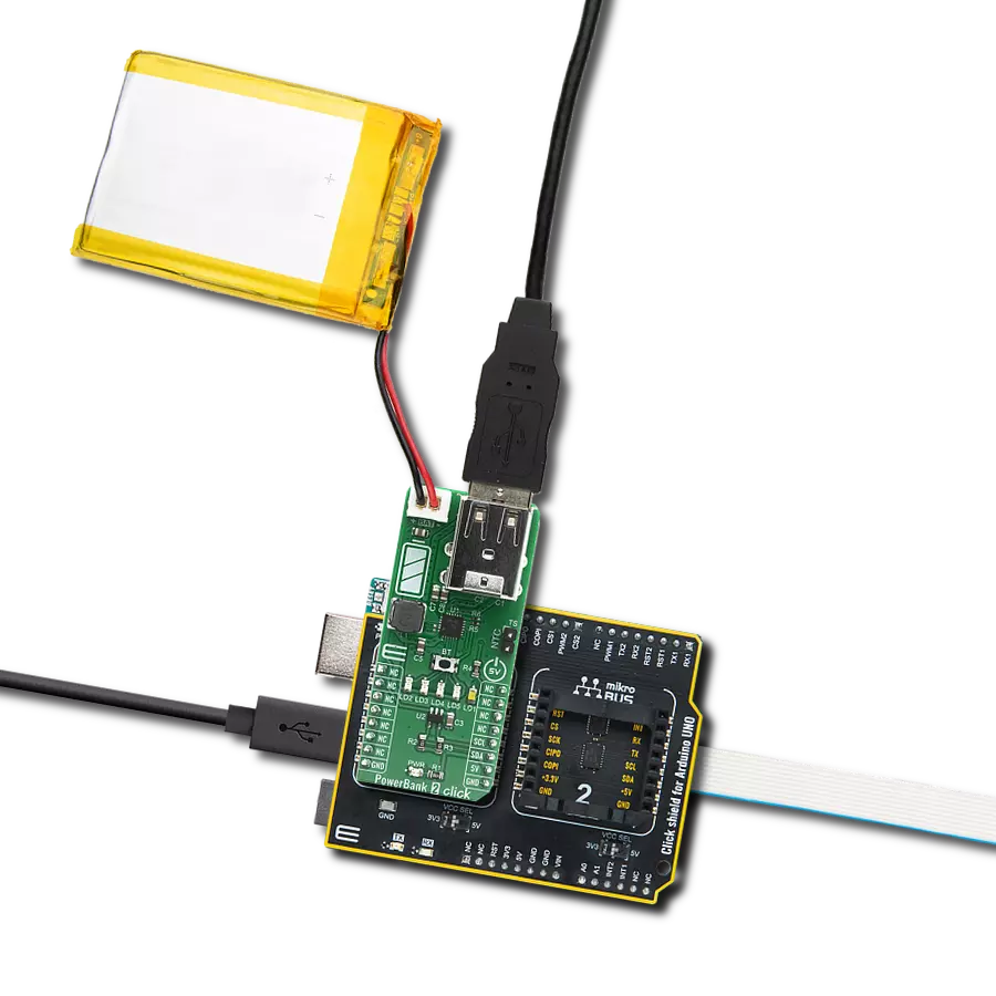
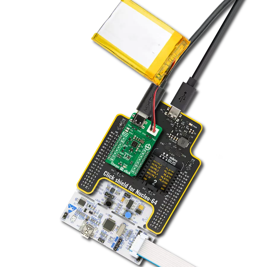
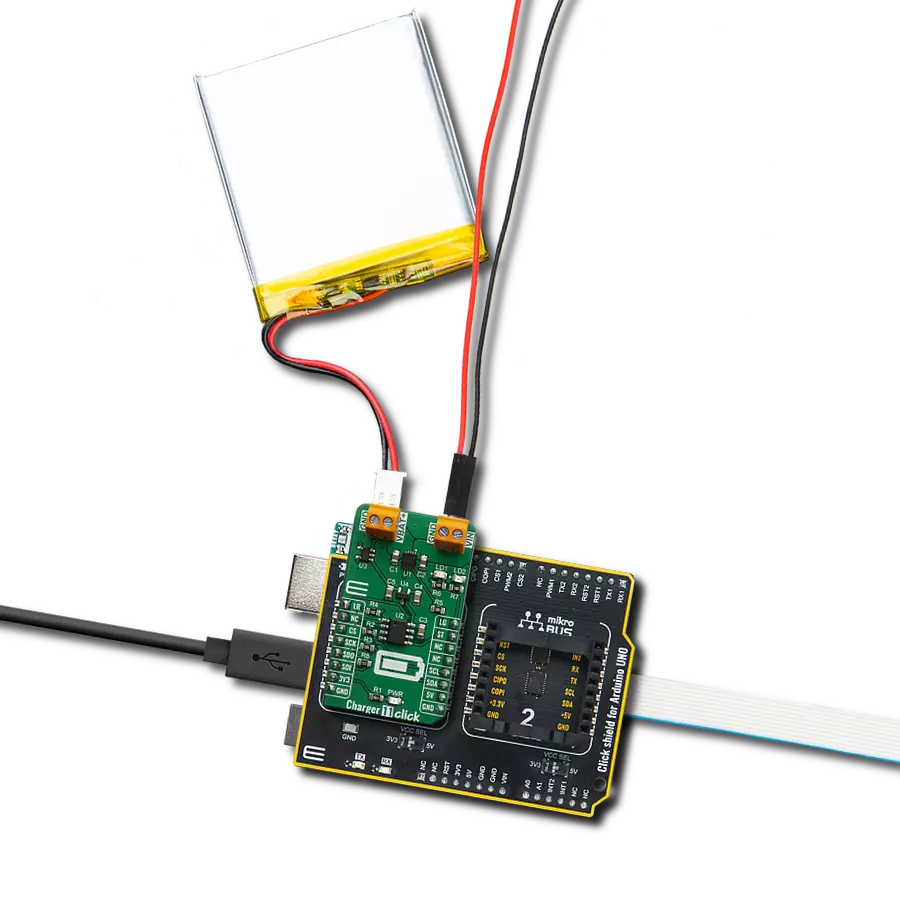
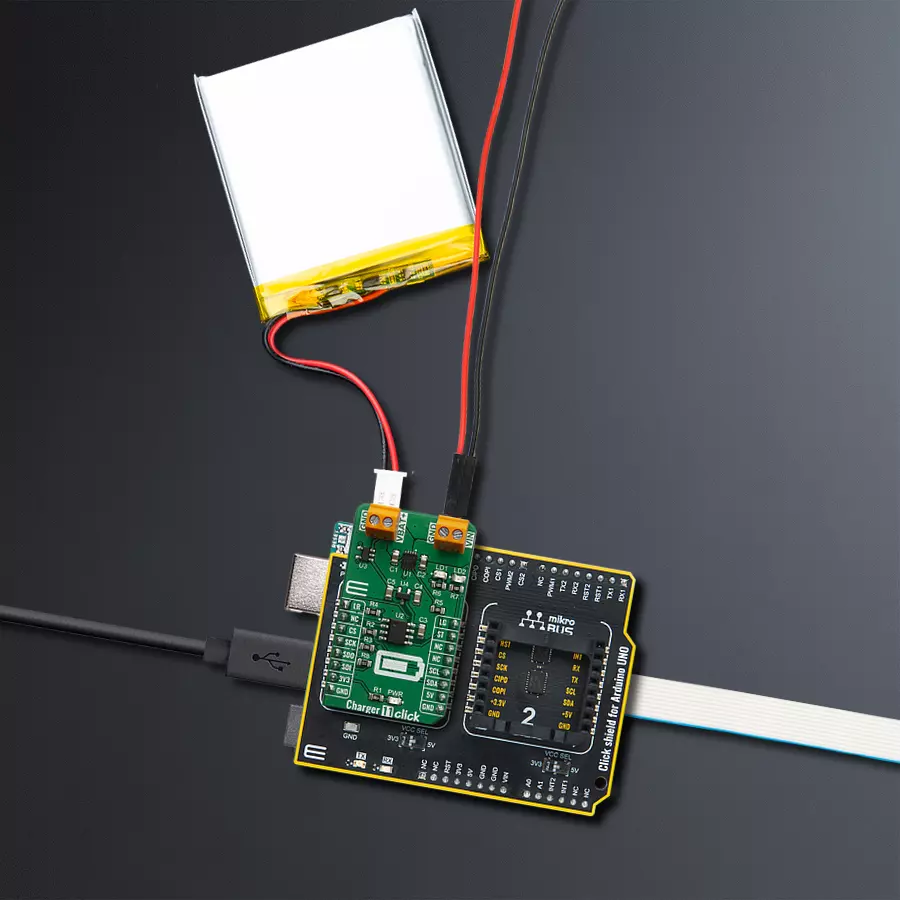
Click Shield for Arduino UNO has two proprietary mikroBUS™ sockets, allowing all the Click board™ devices to be interfaced with the Arduino UNO board without effort. The Arduino Uno, a microcontroller board based on the ATmega328P, provides an affordable and flexible way for users to try out new concepts and build prototypes with the ATmega328P microcontroller from various combinations of performance, power consumption, and features. The Arduino Uno has 14 digital input/output pins (of which six can be used as PWM outputs), six analog inputs, a 16 MHz ceramic resonator (CSTCE16M0V53-R0), a USB connection, a power jack, an ICSP header, and reset button. Most of the ATmega328P microcontroller pins are brought to the IO pins on the left and right edge of the board, which are then connected to two existing mikroBUS™ sockets. This Click Shield also has several switches that perform functions such as selecting the logic levels of analog signals on mikroBUS™ sockets and selecting logic voltage levels of the mikroBUS™ sockets themselves. Besides, the user is offered the possibility of using any Click board™ with the help of existing bidirectional level-shifting voltage translators, regardless of whether the Click board™ operates at a 3.3V or 5V logic voltage level. Once you connect the Arduino UNO board with our Click Shield for Arduino UNO, you can access hundreds of Click boards™, working with 3.3V or 5V logic voltage levels.

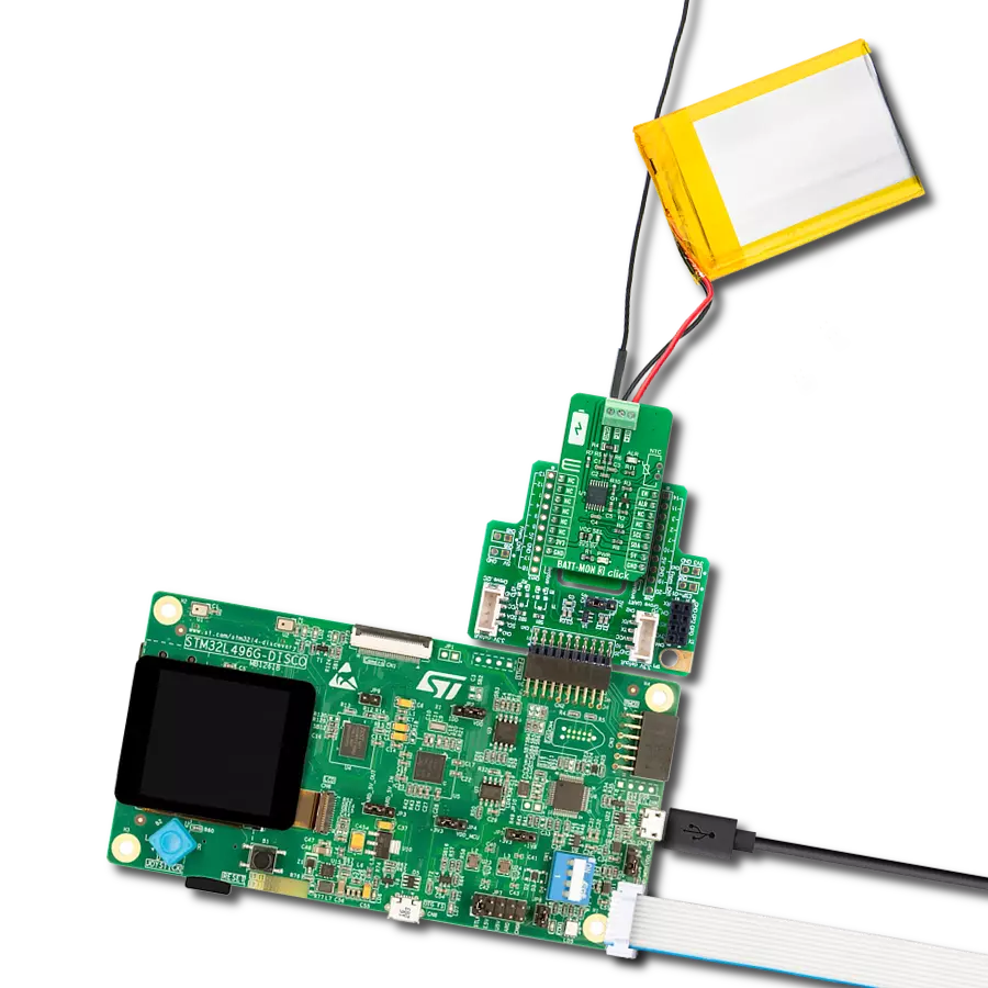
Li-Polymer Battery is the ideal solution for devices that demand a dependable and long-lasting power supply while emphasizing mobility. Its compatibility with mikromedia boards ensures easy integration without additional modifications. With a voltage output of 3.7V, the battery meets the standard requirements of many electronic devices. Additionally, boasting a capacity of 2000mAh, it can store a substantial amount of energy, providing sustained power for extended periods. This feature minimizes the need for frequent recharging or replacement. Overall, the Li-Polymer Battery is a reliable and autonomous power source, ideally suited for devices requiring a stable and enduring energy solution. You can find a more extensive choice of Li-Polymer batteries in our offer.

Used MCU Pins
mikroBUS™ mapper
Take a closer look
Click board™ Schematic

Step by step
Project assembly

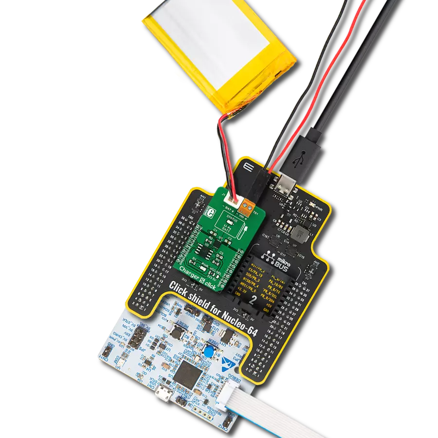
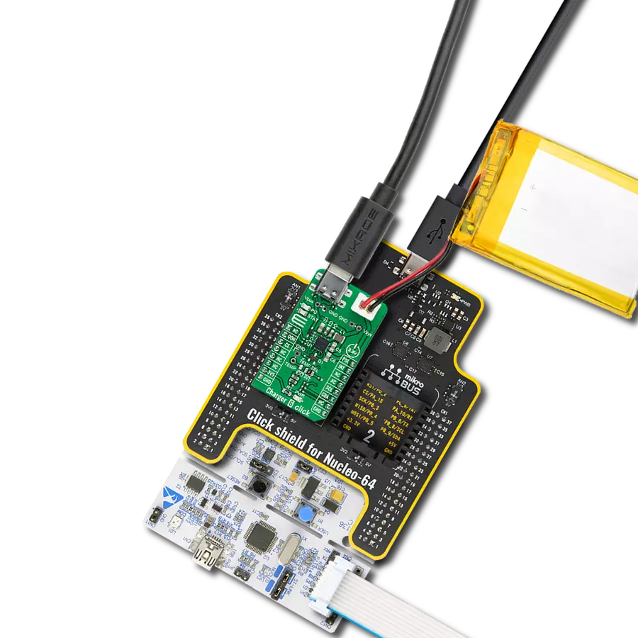
Start by selecting your development board and Click board™. Begin with the Arduino UNO Rev3 as your development board.


Track your results in real time
Application Output
1. Application Output - In Debug mode, the 'Application Output' window enables real-time data monitoring, offering direct insight into execution results. Ensure proper data display by configuring the environment correctly using the provided tutorial.

2. UART Terminal - Use the UART Terminal to monitor data transmission via a USB to UART converter, allowing direct communication between the Click board™ and your development system. Configure the baud rate and other serial settings according to your project's requirements to ensure proper functionality. For step-by-step setup instructions, refer to the provided tutorial.

3. Plot Output - The Plot feature offers a powerful way to visualize real-time sensor data, enabling trend analysis, debugging, and comparison of multiple data points. To set it up correctly, follow the provided tutorial, which includes a step-by-step example of using the Plot feature to display Click board™ readings. To use the Plot feature in your code, use the function: plot(*insert_graph_name*, variable_name);. This is a general format, and it is up to the user to replace 'insert_graph_name' with the actual graph name and 'variable_name' with the parameter to be displayed.

Software Support
Library Description
This library contains API for Charger 11 Click driver.
Key functions:
charger11_spi_increment_wiper- Incrementing wiper positioncharger11_spi_decrement_wiper- Decrementing wiper positioncharger11_i2c_get_volt- Getting output voltage
Open Source
Code example
The complete application code and a ready-to-use project are available through the NECTO Studio Package Manager for direct installation in the NECTO Studio. The application code can also be found on the MIKROE GitHub account.
/*!
 * @file main.c
 * @brief Charger11 Click example
 *
 * # Description
 * This is an example that demonstrates the use of the Charger 11 Click board.
 *
 * The demo application is composed of two sections :
 *
 * ## Application Init
 * Initalizes INT ( ST ), PWM ( LG ), AN ( LR ) pins and SPI, I2C, LOG modules.
 *
 * ## Application Task
 * Waits for user input in order to increment, decrement wiper or log report
 * (Wiper position and Output voltage)
 *
 * Additional Functions :
 * - charger11_log_wiper_position( charger11_t *ctx ) - Logs current Wiper position.
 * - charger11_case_plus( charger11_t *ctx ) - Increments Wiper position.
 * - charger11_case_minus( charger11_t *ctx ) - Decrements Wiper position.
 * - charger11_case_report( charger11_t *ctx ) - Logs current Wiper position and Output voltage.
 *
 * @author Stefan Ilic
 *
 */

#include "board.h"
#include "log.h"
#include "charger11.h"

static charger11_t charger11;
static log_t logger;

/**
 * @brief Charger 11 log wiper position.
 * @details This function reads wiper position and logs it on UART terminal.
 */
void charger11_log_wiper_position( charger11_t *ctx );

/**
 * @brief Charger 11 increase wiper position.
 * @details This function increases wiper position and logs it on UART terminal.
 */
void charger11_case_plus( charger11_t *ctx );

/**
 * @brief Charger 11 decrease wiper position.
 * @details This function decreases wiper position and logs it on UART terminal.
 */
void charger11_case_minus( charger11_t *ctx );

/**
 * @brief Charger 11 log wiper position and voltage.
 * @details This function reads wiper position and voltage and logs them on UART terminal.
 */
void charger11_case_report( charger11_t *ctx );

void application_init ( void ) {
    log_cfg_t log_cfg;  /**< Logger config object. */
    charger11_cfg_t charger11_cfg;  /**< Click config object. */

    /**
     * Logger initialization.
     * Default baud rate: 115200
     * Default log level: LOG_LEVEL_DEBUG
     * @note If USB_UART_RX and USB_UART_TX
     * are defined as HAL_PIN_NC, you will
     * need to define them manually for log to work.
     * See @b LOG_MAP_USB_UART macro definition for detailed explanation.
     */
    LOG_MAP_USB_UART( log_cfg );
    log_init( &logger, &log_cfg );
    log_info( &logger, " Application Init " );

    // Click initialization.
    charger11_cfg_setup( &charger11_cfg );
    CHARGER11_MAP_MIKROBUS( charger11_cfg, MIKROBUS_1 );
    err_t init_flag  = charger11_init( &charger11, &charger11_cfg );
    if ( ( I2C_MASTER_ERROR == init_flag ) || ( SPI_MASTER_ERROR == init_flag ) ) {
        log_error( &logger, " Application Init Error. " );
        log_info( &logger, " Please, run program again... " );

        for ( ; ; );
    }

    log_info( &logger, " Application Task " );
    charger11_case_report( &charger11 );
}

void application_task ( void ) {
    char uart_char;
    if ( log_read( &logger, &uart_char, 1 ) ) {
        switch (uart_char) {
            case '+' : {
                charger11_case_plus( &charger11 );
                break;
            }
            case '-' : {
                charger11_case_minus( &charger11 );
                break;
            }
            case 'r' : {
                charger11_case_report( &charger11 );
                break;
            }
            default : {
                log_printf( &logger, "> Invalid command \r\n" );
                break;
            }
        }
    }
}

int main ( void )
{
    /* Do not remove this line or clock might not be set correctly. */
    #ifdef PREINIT_SUPPORTED
    preinit();
    #endif

    application_init( );

    for ( ; ; )
    {
        application_task( );
    }

    return 0;
}

void charger11_log_wiper_position( charger11_t *ctx ) {
    float wiper_position;
    uint8_t aux_wiper_position;
    aux_wiper_position = charger11_spi_get_wiper_position( ctx );

    wiper_position = ( float ) aux_wiper_position / 255.0;
    wiper_position *= 100.0;
    log_printf( &logger, "> Wiper position : %.2f %%\r\n", wiper_position );
}

void charger11_case_plus( charger11_t *ctx ) {
    log_printf( &logger, "> Wiper incremented\r\n" );
    charger11_spi_increment_wiper( ctx );
    charger11_log_wiper_position( ctx );
}

void charger11_case_minus( charger11_t *ctx ) {
    log_printf( &logger, "> Wiper decremented\r\n" );
    charger11_spi_decrement_wiper( ctx );
    charger11_log_wiper_position( ctx );
}

void charger11_case_report( charger11_t *ctx ) {
    float volt_data;
    charger11_log_wiper_position( ctx );
    volt_data = charger11_i2c_get_volt( ctx, 4096.0 );
    log_printf( &logger, "> Output voltage : %d mV\r\n", ( uint16_t ) volt_data );
}

// ------------------------------------------------------------------------ END
Additional Support
Resources
Category:Battery charger