Create a versatile solution for connecting and controlling various peripherals with MAX7300 and ATmega328P
Expand and conquer: I/O magic for your projects!
Published Feb 14, 2024
Click board™
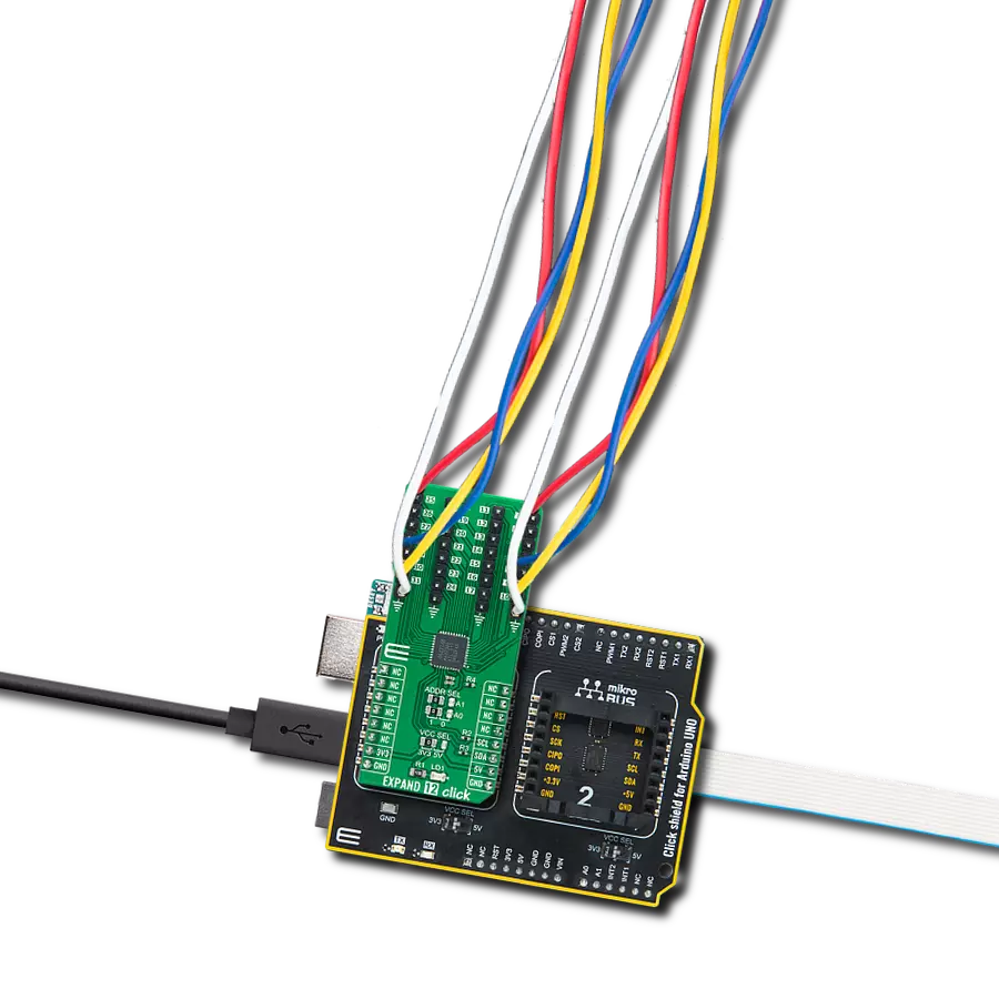
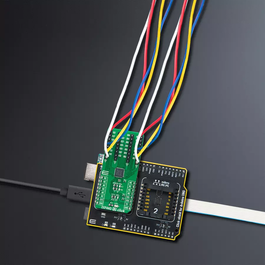
Expand 12 Click
Dev. board
Arduino UNO Rev3
Compiler
NECTO Studio
MCU
ATmega328P
Empower industrial automation systems and embedded solutions with our I/O expander, providing a compact and versatile solution for expanding input and output capabilities
A
A
Hardware Overview
How does it work?
Expand 12 Click is based on the MAX7300, a general-purpose input/output (GPIO) expander from Analog Devices, now part of Analog Devices. This port expander is a simple solution when additional I/Os are needed while keeping interconnections to a minimum. It is particularly great for system monitoring applications, industrial controllers, and portable equipment. The MAX7300 comes in a 28-port configuration, which can be configured to any combination of logic inputs and logic outputs and default to logic inputs on Power-Up. Any I/O port can be configured as a push-pull output (sinking 10mA,
sourcing 4.5mA) or a Schmitt-trigger logic input. Each input has an individually selectable internal pull-up resistor. Additionally, transition detection allows seven ports (from port 24 up to port 30) to be monitored in any maskable combination for changes in their logic status. A detected transition is flagged through a status register bit and an interrupt pin (port 31) if desired. Expand 12 Click communicates with MCU using the standard I2C 2-Wire interface to read data and configure settings with a maximum frequency of 400kHz. Besides, it also allows the choice of the least significant bit of its I2C slave address by
positioning the SMD jumpers labeled ADDR SEL to an appropriate position marked as 1 and 0. This way, the MAX7300 provides the opportunity of the 16 possible different I2C addresses by positioning the SMD jumper to an appropriate position. This Click board™ can operate with either 3.3V or 5V logic voltage levels selected via the VCC SEL jumper. This way, both 3.3V and 5V capable MCUs can use the communication lines properly. Also, this Click board™ comes equipped with a library containing easy-to-use functions and an example code that can be used as a reference for further development.


Features overview
Development board
Arduino UNO is a versatile microcontroller board built around the ATmega328P chip. It offers extensive connectivity options for various projects, featuring 14 digital input/output pins, six of which are PWM-capable, along with six analog inputs. Its core components include a 16MHz ceramic resonator, a USB connection, a power jack, an
ICSP header, and a reset button, providing everything necessary to power and program the board. The Uno is ready to go, whether connected to a computer via USB or powered by an AC-to-DC adapter or battery. As the first USB Arduino board, it serves as the benchmark for the Arduino platform, with "Uno" symbolizing its status as the
first in a series. This name choice, meaning "one" in Italian, commemorates the launch of Arduino Software (IDE) 1.0. Initially introduced alongside version 1.0 of the Arduino Software (IDE), the Uno has since become the foundational model for subsequent Arduino releases, embodying the platform's evolution.

Microcontroller Overview
MCU Card / MCU

Architecture
AVR
MCU Memory (KB)
32
Silicon Vendor
Microchip
Pin count
28
RAM (Bytes)
2048
You complete me!
Accessories
Click Shield for Arduino UNO has two proprietary mikroBUS™ sockets, allowing all the Click board™ devices to be interfaced with the Arduino UNO board without effort. The Arduino Uno, a microcontroller board based on the ATmega328P, provides an affordable and flexible way for users to try out new concepts and build prototypes with the ATmega328P microcontroller from various combinations of performance, power consumption, and features. The Arduino Uno has 14 digital input/output pins (of which six can be used as PWM outputs), six analog inputs, a 16 MHz ceramic resonator (CSTCE16M0V53-R0), a USB connection, a power jack, an ICSP header, and reset button. Most of the ATmega328P microcontroller pins are brought to the IO pins on the left and right edge of the board, which are then connected to two existing mikroBUS™ sockets. This Click Shield also has several switches that perform functions such as selecting the logic levels of analog signals on mikroBUS™ sockets and selecting logic voltage levels of the mikroBUS™ sockets themselves. Besides, the user is offered the possibility of using any Click board™ with the help of existing bidirectional level-shifting voltage translators, regardless of whether the Click board™ operates at a 3.3V or 5V logic voltage level. Once you connect the Arduino UNO board with our Click Shield for Arduino UNO, you can access hundreds of Click boards™, working with 3.3V or 5V logic voltage levels.

Used MCU Pins
mikroBUS™ mapper
Take a closer look
Click board™ Schematic

Step by step
Project assembly

Start by selecting your development board and Click board™. Begin with the Arduino UNO Rev3 as your development board.


Software Support
Library Description
This library contains API for Expand 12 Click driver.
Key functions:
expand12_set_pin_direction- This function sets the direction of the selected pinexpand12_set_pin_value- This function sets the logic level of the selected pinexpand12_read_all_pins_value- This function reads all pins logic levels
Open Source
Code example
The complete application code and a ready-to-use project are available through the NECTO Studio Package Manager for direct installation in the NECTO Studio. The application code can also be found on the MIKROE GitHub account.
/*!
 * @file main.c
 * @brief Expand12 Click example
 *
 * # Description
 * This example demonstrates the use of Expand 12 Click board.
 *
 * The demo application is composed of two sections :
 *
 * ## Application Init
 * Initializes the driver and performs the Click default configuration which sets
 * the first three ports (pins 4-23) as output and the fourth port (pins 24-31) as input with pull-ups.
 *
 * ## Application Task
 * Sets the pins of the first three ports and then reads the status of all pins and
 * displays the result on the USB UART approximately every 100 miliseconds.
 *
 * @author Stefan Filipovic
 *
 */

#include "board.h"
#include "log.h"
#include "expand12.h"

static expand12_t expand12;
static log_t logger;

void application_init ( void )
{
    log_cfg_t log_cfg;  /**< Logger config object. */
    expand12_cfg_t expand12_cfg;  /**< Click config object. */

    /**
     * Logger initialization.
     * Default baud rate: 115200
     * Default log level: LOG_LEVEL_DEBUG
     * @note If USB_UART_RX and USB_UART_TX
     * are defined as HAL_PIN_NC, you will
     * need to define them manually for log to work.
     * See @b LOG_MAP_USB_UART macro definition for detailed explanation.
     */
    LOG_MAP_USB_UART( log_cfg );
    log_init( &logger, &log_cfg );
    log_info( &logger, " Application Init " );

    // Click initialization.
    expand12_cfg_setup( &expand12_cfg );
    EXPAND12_MAP_MIKROBUS( expand12_cfg, MIKROBUS_1 );
    if ( I2C_MASTER_ERROR == expand12_init( &expand12, &expand12_cfg ) )
    {
        log_error( &logger, " Communication init." );
        for ( ; ; );
    }

    if ( EXPAND12_ERROR == expand12_default_cfg ( &expand12 ) )
    {
        log_error( &logger, " Default configuration." );
        for ( ; ; );
    }

    log_info( &logger, " Application Task " );
}

void application_task ( void )
{
    static uint8_t port_value = 0;
    static uint32_t pins_status = 0;

    expand12_set_port_value( &expand12, EXPAND12_PORT_4_7, EXPAND12_ALL_PINS, port_value );
    expand12_set_port_value( &expand12, EXPAND12_PORT_8_15, EXPAND12_ALL_PINS, port_value );
    expand12_set_port_value( &expand12, EXPAND12_PORT_16_23, EXPAND12_ALL_PINS, port_value++ );

    expand12_read_all_pins_value( &expand12, &pins_status );
    log_printf( &logger, " Pins status (32-bit) : 0x%.8LX\r\n\n", pins_status );
    Delay_ms ( 100 );
}

int main ( void )
{
    /* Do not remove this line or clock might not be set correctly. */
    #ifdef PREINIT_SUPPORTED
    preinit();
    #endif

    application_init( );

    for ( ; ; )
    {
        application_task( );
    }

    return 0;
}

// ------------------------------------------------------------------------ END
Additional Support
Resources
Category:Port expander


