Create a reliable tool to monitor, analyze, and manage currents using ACS70331 and ATmega328P
Your pathway to exquisite current measurements

Published Feb 14, 2024
Click board™
Hall Current 4 Click
Dev. board
Arduino UNO Rev3
Compiler
NECTO Studio
MCU
ATmega328P
Tap into efficient current use via our data-driven solution, leading to cost savings, productivity gains, and operational excellence
A
A
Hardware Overview
How does it work?
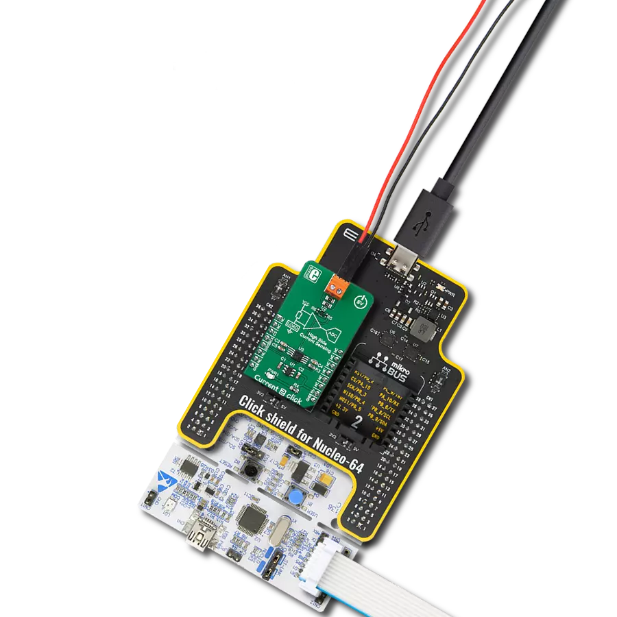
Hall Current 4 Click is based on the ACS70331, a current sensor from Allegro Microsystems, and the 12-bit ADC marked MCP3221, produced by Microchip. The ACS70331 uses GMR elements to indirectly measure the current flowing through the primary conductor of the IC by sensing the field produced by this current. This IC utilizes the field generated by the current passing through the primary conductor affects the voltage across the GMR sensor. The GMR sensor voltage changes even with a low field strength, which makes the ACS70331 very suitable for accurate
measurements of lower currents. However, the saturation happens quite soon after, making it unsuitable for higher currents. The ACS70331 has a sensitivity of 200 mV/A and can measure the current in the range from -5A to +5A. Considering that the operative range of the ACS70331 is approximately 1 MHz, the output voltage variations with the load current are quite fast with no latency. The output voltage from the ACS70331 is fed to the input of the analog-digital converter (ADC), which allows the reading of the conversion data via the I2C interface. The ACS70331 has a small primary
conductor resistance of 1.1 mΩ, resulting in low power dissipation and low-temperature rise due to current flow through the sensor. The sensor has no physical contact with the output pins on the chip as it operates exclusively by the principle of the field generated by the current, which runs through the input pins (primary conductor). The load voltage at the input pins is isolated from the rest of the chip. However, it is unsafe to use at voltages higher than 100V.


Features overview
Development board
Arduino UNO is a versatile microcontroller board built around the ATmega328P chip. It offers extensive connectivity options for various projects, featuring 14 digital input/output pins, six of which are PWM-capable, along with six analog inputs. Its core components include a 16MHz ceramic resonator, a USB connection, a power jack, an
ICSP header, and a reset button, providing everything necessary to power and program the board. The Uno is ready to go, whether connected to a computer via USB or powered by an AC-to-DC adapter or battery. As the first USB Arduino board, it serves as the benchmark for the Arduino platform, with "Uno" symbolizing its status as the
first in a series. This name choice, meaning "one" in Italian, commemorates the launch of Arduino Software (IDE) 1.0. Initially introduced alongside version 1.0 of the Arduino Software (IDE), the Uno has since become the foundational model for subsequent Arduino releases, embodying the platform's evolution.

Microcontroller Overview
MCU Card / MCU

Architecture
AVR
MCU Memory (KB)
32
Silicon Vendor
Microchip
Pin count
28
RAM (Bytes)
2048
You complete me!
Accessories
Click Shield for Arduino UNO has two proprietary mikroBUS™ sockets, allowing all the Click board™ devices to be interfaced with the Arduino UNO board without effort. The Arduino Uno, a microcontroller board based on the ATmega328P, provides an affordable and flexible way for users to try out new concepts and build prototypes with the ATmega328P microcontroller from various combinations of performance, power consumption, and features. The Arduino Uno has 14 digital input/output pins (of which six can be used as PWM outputs), six analog inputs, a 16 MHz ceramic resonator (CSTCE16M0V53-R0), a USB connection, a power jack, an ICSP header, and reset button. Most of the ATmega328P microcontroller pins are brought to the IO pins on the left and right edge of the board, which are then connected to two existing mikroBUS™ sockets. This Click Shield also has several switches that perform functions such as selecting the logic levels of analog signals on mikroBUS™ sockets and selecting logic voltage levels of the mikroBUS™ sockets themselves. Besides, the user is offered the possibility of using any Click board™ with the help of existing bidirectional level-shifting voltage translators, regardless of whether the Click board™ operates at a 3.3V or 5V logic voltage level. Once you connect the Arduino UNO board with our Click Shield for Arduino UNO, you can access hundreds of Click boards™, working with 3.3V or 5V logic voltage levels.

Used MCU Pins
mikroBUS™ mapper
Take a closer look
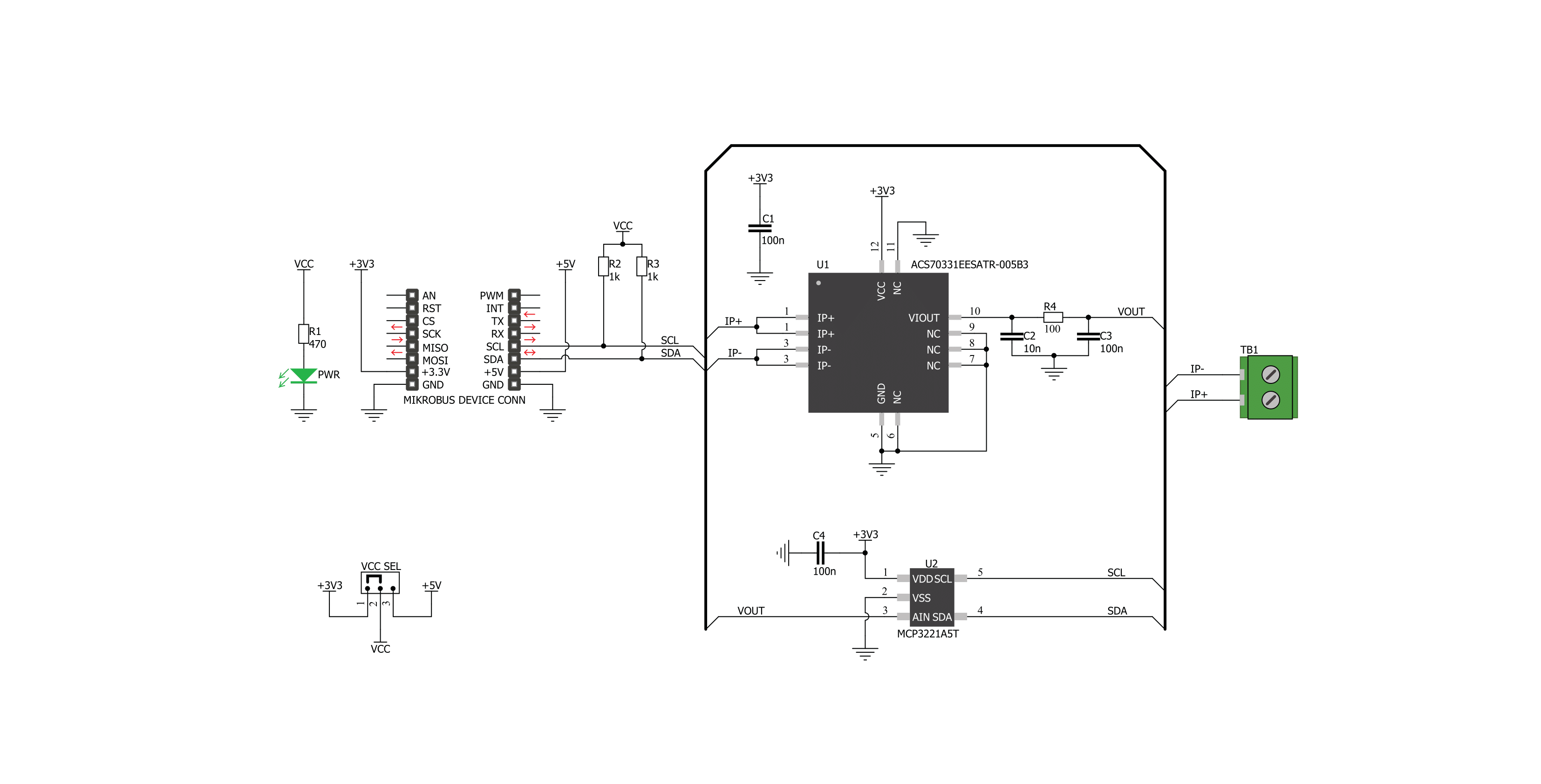
Click board™ Schematic
Step by step
Project assembly

Start by selecting your development board and Click board™. Begin with the Arduino UNO Rev3 as your development board.


Track your results in real time
Application Output
1. Application Output - In Debug mode, the 'Application Output' window enables real-time data monitoring, offering direct insight into execution results. Ensure proper data display by configuring the environment correctly using the provided tutorial.

2. UART Terminal - Use the UART Terminal to monitor data transmission via a USB to UART converter, allowing direct communication between the Click board™ and your development system. Configure the baud rate and other serial settings according to your project's requirements to ensure proper functionality. For step-by-step setup instructions, refer to the provided tutorial.

3. Plot Output - The Plot feature offers a powerful way to visualize real-time sensor data, enabling trend analysis, debugging, and comparison of multiple data points. To set it up correctly, follow the provided tutorial, which includes a step-by-step example of using the Plot feature to display Click board™ readings. To use the Plot feature in your code, use the function: plot(*insert_graph_name*, variable_name);. This is a general format, and it is up to the user to replace 'insert_graph_name' with the actual graph name and 'variable_name' with the parameter to be displayed.

Software Support
Library Description
This library contains API for Hall Current 4 Click driver.
Key functions:
hallcurrent4_get_current_data- This function reads current in mAhallcurrent4_get_raw_data- This function reads raw (ADC) current data
Open Source
Code example
The complete application code and a ready-to-use project are available through the NECTO Studio Package Manager for direct installation in the NECTO Studio. The application code can also be found on the MIKROE GitHub account.
/*!
 * \file
 * \brief HallCurrent4 Click example
 *
 * # Description
 * Demo application shows is reading current data in mA using Hall current 4 click.
 *
 * The demo application is composed of two sections :
 *
 * ## Application Init
 * Configuring clicks and log objects.
 *
 * ## Application Task
 * Reads Current value in mA and logs this data to USBUART every 1 sec.
 *
 * \author Katarina Perendic
 *
 */
// ------------------------------------------------------------------- INCLUDES

#include "board.h"
#include "log.h"
#include "hallcurrent4.h"

// ------------------------------------------------------------------ VARIABLES

static hallcurrent4_t hallcurrent4;
static log_t logger;

// ------------------------------------------------------ APPLICATION FUNCTIONS

void application_init ( void )
{
    log_cfg_t log_cfg;
    hallcurrent4_cfg_t cfg;

    /**
     * Logger initialization.
     * Default baud rate: 115200
     * Default log level: LOG_LEVEL_DEBUG
     * @note If USB_UART_RX and USB_UART_TX
     * are defined as HAL_PIN_NC, you will
     * need to define them manually for log to work.
     * See @b LOG_MAP_USB_UART macro definition for detailed explanation.
     */
    LOG_MAP_USB_UART( log_cfg );
    log_init( &logger, &log_cfg );
    log_info( &logger, "---- Application Init ----" );

    //  Click initialization.

    hallcurrent4_cfg_setup( &cfg );
    HALLCURRENT4_MAP_MIKROBUS( cfg, MIKROBUS_1 );
    hallcurrent4_init( &hallcurrent4, &cfg );
}

void application_task ( void )
{
    float current;

    current = hallcurrent4_get_current_data( &hallcurrent4 );

    log_printf( &logger, " >> Current value: %.2f mA\r\n", current );
    log_printf( &logger, " ------------------------- \r\n" );
    Delay_ms( 1000 );
}

void main ( void )
{
    application_init( );

    for ( ; ; )
    {
        application_task( );
    }
}


// ------------------------------------------------------------------------ END
Additional Support
Resources
Category:Current sensor