Maximize efficiency with precise current measurement using FAN4010 and TM4C129ENCPDT
Precision for every Amp!

Published Aug 10, 2023
Click board™
Current 2 Click
Dev. board
Fusion for Tiva v8
Compiler
NECTO Studio
MCU
TM4C129ENCPDT
Employ our precise current measurement solution to streamline operations, maximize energy utilization, and ensure system reliability
A
A
Hardware Overview
How does it work?
Current 2 Click is based on the FAN4010, a high-side current sensor by ON Semiconductor. This integrated circuit is a transimpedance amplifier suitable for the current sensing through the shunt resistor on the high side, between the power supply and the connected load. This allows the short circuit on the load to be sensed and will not disturb the GND reference of the connected load since the shunt resistor between the load negative connection terminal and the GND is avoided. These advantages benefit battery charging applications and gauges since short circuit detection is important. Also, the negative terminal of the battery has to stay on the same potential as the GND for the temperature output to be accurate, which is impossible with the low-side shunt resistor. A similar schematic could be designed using only operational amplifiers; however, due to the high inaccuracy of such a design (as the offset voltage of a typical
operational amplifier can greatly affect the output current, especially after the amplification is applied) and the low common mode voltage that typical operational amplifier can withstand, specialized current sensing amplifier ICs (CSA) such as the FAN4010, are used instead. The FAN4010 features an extremely low current offset of only 2 µA, which allows very accurate measurement within the 0.2% margin. The transconductance ratio at the output of the FAN4010 is 10mA/V, where V represents the voltage across the shunt resistor. The current at the output linearly depends on the current through the load. Using the appropriate resistor between the output and the GND, this current can be scaled to a proper voltage level to be used as the input for the A/D converter, the MCP3001, a 10-bit A/D converter (ADC) with SPI interface from Microchip. It is a high-performance, low-noise single-supply ADC that can deliver up to 200,000
samples per second (200 kbps). This makes it well-suited for fast-monitoring applications. It is also equipped with the reference input pin, allowing it to use an accurate voltage reference, which ensures very high sampling accuracy. Combined with the MCP1501-20 IC, a high-precision, buffered voltage reference of 2.048V, it is used with enough headroom to sample load current up to 4 A (4 A = 2 V at the ADC input). The calculation formulas can be derived from the datasheet of the FAN4010. However, it is unnecessary to perform any calculations if using mikroSDK-compatible functions provided for this Click board™. These functions already contain all the necessary calculations and output the current through the connected load directly in physical units [mA]. The included example demonstrates their practical usage.

Features overview
Development board
Fusion for TIVA v8 is a development board specially designed for the needs of rapid development of embedded applications. It supports a wide range of microcontrollers, such as different 32-bit ARM® Cortex®-M based MCUs from Texas Instruments, regardless of their number of pins, and a broad set of unique functions, such as the first-ever embedded debugger/programmer over a WiFi network. The development board is well organized and designed so that the end-user has all the necessary elements, such as switches, buttons, indicators, connectors, and others, in one place. Thanks to innovative manufacturing technology, Fusion for TIVA v8 provides a fluid and immersive working experience, allowing access
anywhere and under any circumstances at any time. Each part of the Fusion for TIVA v8 development board contains the components necessary for the most efficient operation of the same board. An advanced integrated CODEGRIP programmer/debugger module offers many valuable programming/debugging options, including support for JTAG, SWD, and SWO Trace (Single Wire Output)), and seamless integration with the Mikroe software environment. Besides, it also includes a clean and regulated power supply module for the development board. It can use a wide range of external power sources, including a battery, an external 12V power supply, and a power source via the USB Type-C (USB-C) connector.
Communication options such as USB-UART, USB HOST/DEVICE, CAN (on the MCU card, if supported), and Ethernet is also included. In addition, it also has the well-established mikroBUS™ standard, a standardized socket for the MCU card (SiBRAIN standard), and two display options for the TFT board line of products and character-based LCD. Fusion for TIVA v8 is an integral part of the Mikroe ecosystem for rapid development. Natively supported by Mikroe software tools, it covers many aspects of prototyping and development thanks to a considerable number of different Click boards™ (over a thousand boards), the number of which is growing every day.

Microcontroller Overview
MCU Card / MCU

Type
8th Generation
Architecture
ARM Cortex-M4
MCU Memory (KB)
1024
Silicon Vendor
Texas Instruments
Pin count
128
RAM (Bytes)
262144
Used MCU Pins
mikroBUS™ mapper
Take a closer look
Click board™ Schematic

Step by step
Project assembly

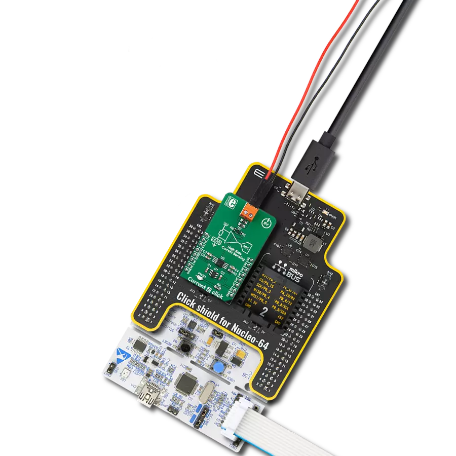
Start by selecting your development board and Click board™. Begin with the Fusion for Tiva v8 as your development board.


Track your results in real time
Application Output
1. Application Output - In Debug mode, the 'Application Output' window enables real-time data monitoring, offering direct insight into execution results. Ensure proper data display by configuring the environment correctly using the provided tutorial.

2. UART Terminal - Use the UART Terminal to monitor data transmission via a USB to UART converter, allowing direct communication between the Click board™ and your development system. Configure the baud rate and other serial settings according to your project's requirements to ensure proper functionality. For step-by-step setup instructions, refer to the provided tutorial.

3. Plot Output - The Plot feature offers a powerful way to visualize real-time sensor data, enabling trend analysis, debugging, and comparison of multiple data points. To set it up correctly, follow the provided tutorial, which includes a step-by-step example of using the Plot feature to display Click board™ readings. To use the Plot feature in your code, use the function: plot(*insert_graph_name*, variable_name);. This is a general format, and it is up to the user to replace 'insert_graph_name' with the actual graph name and 'variable_name' with the parameter to be displayed.

Software Support
Library Description
This library contains API for Current 2 Click driver.
Key functions:
current2_get_adc- Get ADC functioncurrent2_get_average_adc- Get averaged ADC functioncurrent2_get_current- Get current function
Open Source
Code example
The complete application code and a ready-to-use project are available through the NECTO Studio Package Manager for direct installation in the NECTO Studio. The application code can also be found on the MIKROE GitHub account.
/*!
* \file
* \brief current2 Click example
*
* # Description
* This application measures current.
*
* The demo application is composed of two sections :
*
* ## Application Init
* Initializes SPI interface in Mode 0
*
* ## Application Task
* Reads the current averaged result of 20 samples and
* gets this result in a proper value [mA]. Repeats the current reading every 500ms.
*
* \author MikroE Team
*
*/
// ------------------------------------------------------------------- INCLUDES
#include "board.h"
#include "log.h"
#include "current2.h"
// ------------------------------------------------------------------ VARIABLES
static current2_t current;
static log_t logger;
// ------------------------------------------------------ APPLICATION FUNCTIONS
void application_init ( void )
{
log_cfg_t log_cfg;
current2_cfg_t cfg;
/**
* Logger initialization.
* Default baud rate: 115200
* Default log level: LOG_LEVEL_DEBUG
* @note If USB_UART_RX and USB_UART_TX
* are defined as HAL_PIN_NC, you will
* need to define them manually for log to work.
* See @b LOG_MAP_USB_UART macro definition for detailed explanation.
*/
LOG_MAP_USB_UART( log_cfg );
log_init( &logger, &log_cfg );
log_info( &logger, "---- Application Init ----" );
// Click initialization.
current2_cfg_setup( &cfg );
CURRENT2_MAP_MIKROBUS( cfg, MIKROBUS_1 );
current2_init( ¤t, &cfg );
Delay_ms ( 300 );
log_printf( &logger, "Current 2 is initialized \r\n \r\n" );
}
void application_task ( void )
{
uint16_t tmp;
tmp = current2_get_current( ¤t, 20 );
log_printf( &logger, "Current : %d mA \r\n", tmp );
Delay_ms ( 500 );
}
int main ( void )
{
/* Do not remove this line or clock might not be set correctly. */
#ifdef PREINIT_SUPPORTED
preinit();
#endif
application_init( );
for ( ; ; )
{
application_task( );
}
return 0;
}
// ------------------------------------------------------------------------ END