Achieve precise detection of movements, crucial for motion-based applications, with ICM-42670-P and ATmega328P
Motion tracking and orientation detection based on a 6-axis MEMS MotionTracking IMU

Published Mar 15, 2024
Click board™
6DOF IMU 22 Click
Dev. board
Arduino UNO Rev3
Compiler
NECTO Studio
MCU
ATmega328P
Accurately track and measure movements and orientations of an object by detecting how fast and in which direction it's moving or tilting
A
A
Hardware Overview
How does it work?
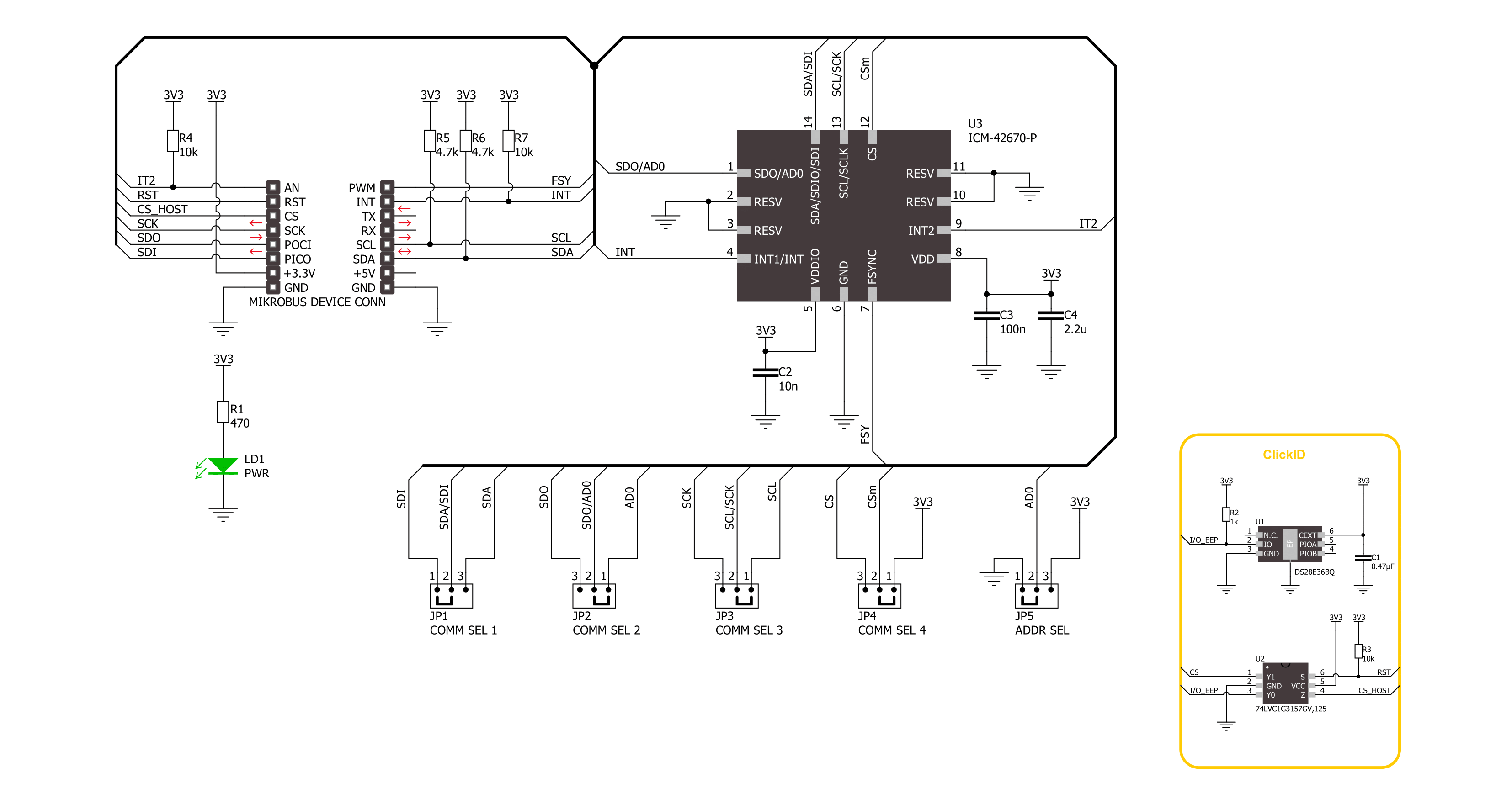
6DOF IMU 22 Click is based on the ICM-42670-P, a state-of-the-art 6-axis MEMS MotionTracking IMU from TDK InvenSense. This central component incorporates both a 3-axis gyroscope and a 3-axis accelerometer, making it an exceptional tool for precise motion tracking. It has a versatile host interface compatible with I2C and SPI serial communication protocols, a sizeable 2.25Kbytes FIFO, and two customizable interrupts supporting a wake-on-motion feature to reduce power consumption significantly. The gyroscope and accelerometer offer a range of programmable full-scale range settings, ensuring flexibility across various applications. The gyroscope supports four programmable full-scale range settings from ±250dps to ±2000dps, and the accelerometer supports four programmable full-scale range
settings from ±2g to ±16g. The ICM-42670-P stands out in its class for having the lowest noise levels and unparalleled stability under temperature fluctuations, physical shocks, or offsets caused by soldering or bending. It also offers protection against noise from vibrations outside its frequency band. Adding to its impressive feature set are an on-board APEX Motion Processing engine for advanced gesture and step recognition, programmable digital filters, and an integrated temperature sensor, making it ideally suited for creating wearables, smart home devices, robotics, and immersive AR/VR experiences. 6DOF IMU 22 Click supports both I2C and SPI interfaces, enabling communication at speeds up to 1MHz and 24MHz, respectively. Users can select the desired communication protocol by placing SMD jumpers
on the COMM SEL section, ensuring all jumpers align on the same side to avoid potential issues. For I2C usage, the device allows the adjustment of its I2C slave address's least significant bit via an SMD jumper marked as ADDR SEL. Additionally, the board features a data frame sync input pin routed to the FSY pin on the mikroBUS™ socket and two interrupt pins linked to the INT and IT2 pins, enabling the host MCU to detect user-specified events through the I2C/SPI interface. This Click board™ can be operated only with a 3.3V logic voltage level. The board must perform appropriate logic voltage level conversion before using MCUs with different logic levels. Also, it comes equipped with a library containing functions and an example code that can be used as a reference for further development.

Features overview
Development board
Arduino UNO is a versatile microcontroller board built around the ATmega328P chip. It offers extensive connectivity options for various projects, featuring 14 digital input/output pins, six of which are PWM-capable, along with six analog inputs. Its core components include a 16MHz ceramic resonator, a USB connection, a power jack, an
ICSP header, and a reset button, providing everything necessary to power and program the board. The Uno is ready to go, whether connected to a computer via USB or powered by an AC-to-DC adapter or battery. As the first USB Arduino board, it serves as the benchmark for the Arduino platform, with "Uno" symbolizing its status as the
first in a series. This name choice, meaning "one" in Italian, commemorates the launch of Arduino Software (IDE) 1.0. Initially introduced alongside version 1.0 of the Arduino Software (IDE), the Uno has since become the foundational model for subsequent Arduino releases, embodying the platform's evolution.

Microcontroller Overview
MCU Card / MCU

Architecture
AVR
MCU Memory (KB)
32
Silicon Vendor
Microchip
Pin count
28
RAM (Bytes)
2048
You complete me!
Accessories
Click Shield for Arduino UNO has two proprietary mikroBUS™ sockets, allowing all the Click board™ devices to be interfaced with the Arduino UNO board without effort. The Arduino Uno, a microcontroller board based on the ATmega328P, provides an affordable and flexible way for users to try out new concepts and build prototypes with the ATmega328P microcontroller from various combinations of performance, power consumption, and features. The Arduino Uno has 14 digital input/output pins (of which six can be used as PWM outputs), six analog inputs, a 16 MHz ceramic resonator (CSTCE16M0V53-R0), a USB connection, a power jack, an ICSP header, and reset button. Most of the ATmega328P microcontroller pins are brought to the IO pins on the left and right edge of the board, which are then connected to two existing mikroBUS™ sockets. This Click Shield also has several switches that perform functions such as selecting the logic levels of analog signals on mikroBUS™ sockets and selecting logic voltage levels of the mikroBUS™ sockets themselves. Besides, the user is offered the possibility of using any Click board™ with the help of existing bidirectional level-shifting voltage translators, regardless of whether the Click board™ operates at a 3.3V or 5V logic voltage level. Once you connect the Arduino UNO board with our Click Shield for Arduino UNO, you can access hundreds of Click boards™, working with 3.3V or 5V logic voltage levels.

Used MCU Pins
mikroBUS™ mapper
Take a closer look
Click board™ Schematic
Step by step
Project assembly

Start by selecting your development board and Click board™. Begin with the Arduino UNO Rev3 as your development board.


Software Support
Library Description
This library contains API for 6DOF IMU 22 Click driver.
Key functions:
c6dofimu22_read_data- This function reads the accelerometer, gyroscope, and temperature measurement datac6dofimu22_get_int1_pin- This function returns the INT1 pin logic statec6dofimu22_clear_data_ready- This function clears the data ready interrupt by reading the INT_STATUS_DRDY register
Open Source
Code example
The complete application code and a ready-to-use project are available through the NECTO Studio Package Manager for direct installation in the NECTO Studio. The application code can also be found on the MIKROE GitHub account.
/*!
 * @file main.c
 * @brief 6DOF IMU 22 Click example
 *
 * # Description
 * This example demonstrates the use of 6DOF IMU 22 Click board by reading and displaying
 * the accelerometer and gyroscope data (X, Y, and Z axis) as well as a temperature measurement
 * in degrees Celsius.
 *
 * The demo application is composed of two sections :
 *
 * ## Application Init
 * Initializes the driver and performs the Click default configuration.
 *
 * ## Application Task
 * Waits for a data ready indication and then reads the accelerometer, gyroscope, and temperature
 * measurements. The results are displayed on the USB UART every 80ms as per the accel and gyro
 * output data rate which is set to 12.5 Hz.
 *
 * @author Stefan Filipovic
 *
 */

#include "board.h"
#include "log.h"
#include "c6dofimu22.h"

static c6dofimu22_t c6dofimu22;
static log_t logger;

void application_init ( void )
{
    log_cfg_t log_cfg;  /**< Logger config object. */
    c6dofimu22_cfg_t c6dofimu22_cfg;  /**< Click config object. */

    /**
     * Logger initialization.
     * Default baud rate: 115200
     * Default log level: LOG_LEVEL_DEBUG
     * @note If USB_UART_RX and USB_UART_TX
     * are defined as HAL_PIN_NC, you will
     * need to define them manually for log to work.
     * See @b LOG_MAP_USB_UART macro definition for detailed explanation.
     */
    LOG_MAP_USB_UART( log_cfg );
    log_init( &logger, &log_cfg );
    log_info( &logger, " Application Init " );

    // Click initialization.
    c6dofimu22_cfg_setup( &c6dofimu22_cfg );
    C6DOFIMU22_MAP_MIKROBUS( c6dofimu22_cfg, MIKROBUS_1 );
    err_t init_flag = c6dofimu22_init( &c6dofimu22, &c6dofimu22_cfg );
    if ( ( I2C_MASTER_ERROR == init_flag ) || ( SPI_MASTER_ERROR == init_flag ) )
    {
        log_error( &logger, " Communication init." );
        for ( ; ; );
    }

    if ( C6DOFIMU22_ERROR == c6dofimu22_default_cfg ( &c6dofimu22 ) )
    {
        log_error( &logger, " Default configuration." );
        for ( ; ; );
    }

    log_info( &logger, " Application Task " );
}

void application_task ( void )
{
    static c6dofimu22_data_t meas_data;
    if ( !c6dofimu22_get_int1_pin ( &c6dofimu22 ) )
    {
        c6dofimu22_clear_data_ready ( &c6dofimu22 );
        if ( C6DOFIMU22_OK == c6dofimu22_read_data ( &c6dofimu22, &meas_data ) )
        {
            log_printf ( &logger, " Accel X: %.2f g\r\n", meas_data.accel.x );
            log_printf ( &logger, " Accel Y: %.2f g\r\n", meas_data.accel.y );
            log_printf ( &logger, " Accel Z: %.2f g\r\n", meas_data.accel.z );
            log_printf ( &logger, " Gyro X: %.1f dps\r\n", meas_data.gyro.x );
            log_printf ( &logger, " Gyro Y: %.1f dps\r\n", meas_data.gyro.y );
            log_printf ( &logger, " Gyro Z: %.1f dps\r\n", meas_data.gyro.z );
            log_printf ( &logger, " Temperature: %.2f C\r\n\n", meas_data.temperature );
        }
    }
}

int main ( void )
{
    /* Do not remove this line or clock might not be set correctly. */
    #ifdef PREINIT_SUPPORTED
    preinit();
    #endif

    application_init( );

    for ( ; ; )
    {
        application_task( );
    }

    return 0;
}

// ------------------------------------------------------------------------ END
Additional Support
Resources
Category:Motion


