Provide accurate and reliable motion tracking for a variety of applications with the IIM-20670 and ATmega328P
SmartIndustrial™ 6-axis MotionTracking solution

Published Aug 08, 2024
Click board™
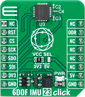
6DOF IMU 23 Click
Dev. board
Arduino UNO Rev3
Compiler
NECTO Studio
MCU
ATmega328P
Accurately measure acceleration and angular rate in three dimensions (X, Y, Z axes) for precise motion tracking
A
A
Hardware Overview
How does it work?
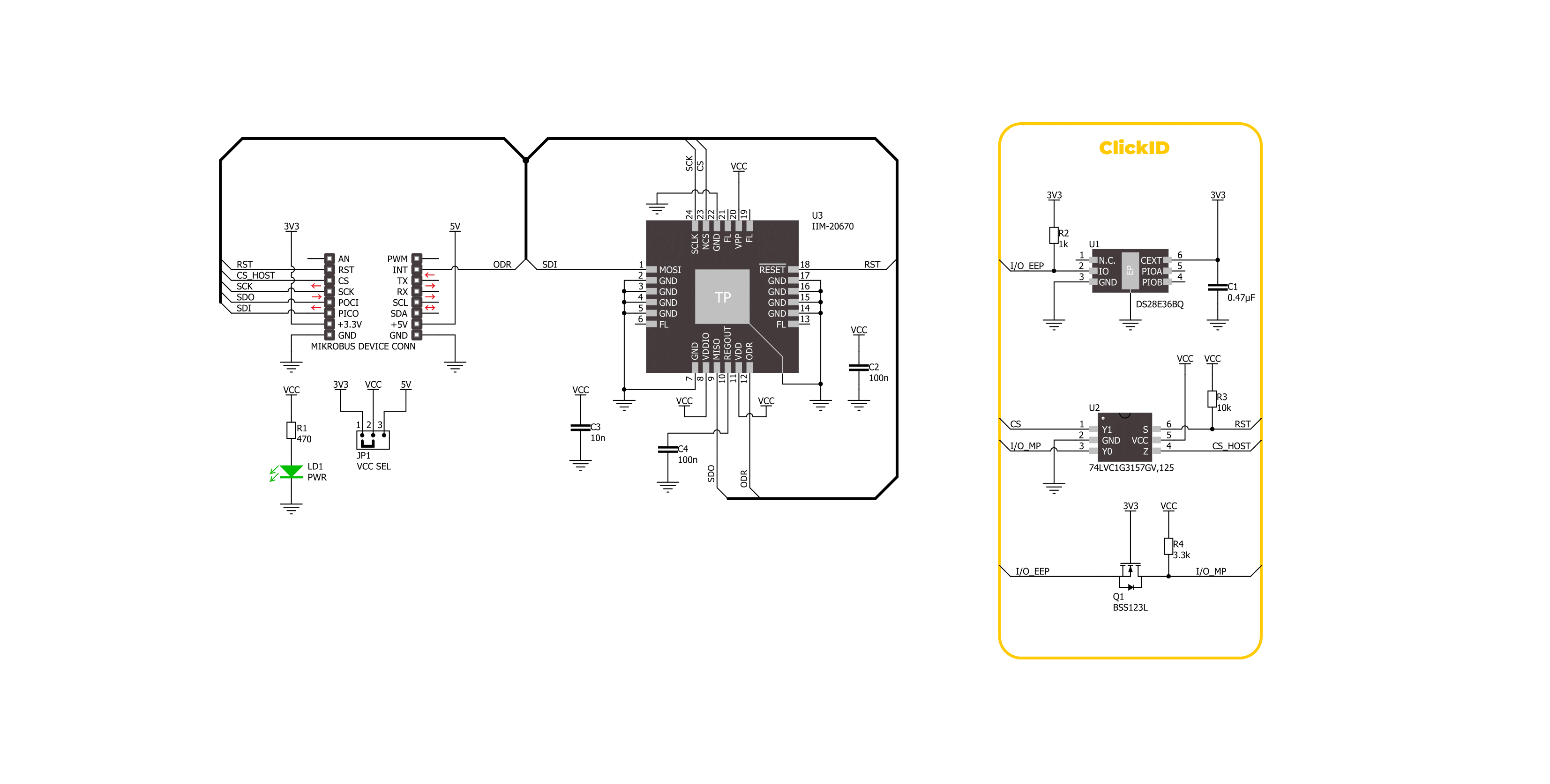
6DOF IMU 23 Click is based on the IIM-20670, a high-performance SmartIndustrial™ 6-axis MotionTracking device from TDK InvenSense that combines a 3-axis gyroscope and a 3-axis accelerometer in a compact plastic package. Using InvenSense's patented CMOS-MEMS fabrication platform, this component provides exceptional integration and performance within a small form factor. The gyroscope features a user-programmable full-scale range of up to ±1966 dps, with guaranteed accuracy up to ±300 dps, while the accelerometer offers a user-programmable full-scale range of ±2g to ±65g, with accuracy guaranteed up to ±36g. Key features of the IIM-20670 also include a 10MHz SPI interface, a shock-tolerant structure capable of withstanding up to 10,000 g, and minimal offset and sensitivity
variation across temperature changes. Additionally, the IIM-20670 boasts on-chip 16-bit ADCs, programmable digital filters, a selectable power supply, and a current consumption below 10mA in all operating conditions. This robust feature set makes it ideal for various industrial applications, including navigation, platform stabilization, asset tracking, robotics, industrial automation, smart transportation, and machinery for agriculture and construction. As mentioned, the 6DOF IMU 23 Click communicates with the host MCU through a robust and efficient 4-wire SPI interface, which supports a maximum clock frequency of 10MHz, ensuring fast and reliable data transfer. This interface is critical for enabling precise and synchronized communication between the sensor and the host MCU. In addition to the standard communication
pins, this Click board™ features a dedicated RST pin, which performs the resetting of the IIM-20670, allowing for quick reinitialization and troubleshooting. Furthermore, it also includes an ODR (Output Data Ready) pin that plays a vital role in providing synchronous sensor data readings by signaling when new data is available, thereby ensuring that the host MCU can promptly and accurately read sensor data without unnecessary delays. This Click board™ can operate with either 3.3V or 5V logic voltage levels selected via the VCC SEL jumper. This way, both 3.3V and 5V capable MCUs can use the communication lines properly. Also, this Click board™ comes equipped with a library containing easy-to-use functions and an example code that can be used as a reference for further development.

Features overview
Development board
Arduino UNO is a versatile microcontroller board built around the ATmega328P chip. It offers extensive connectivity options for various projects, featuring 14 digital input/output pins, six of which are PWM-capable, along with six analog inputs. Its core components include a 16MHz ceramic resonator, a USB connection, a power jack, an
ICSP header, and a reset button, providing everything necessary to power and program the board. The Uno is ready to go, whether connected to a computer via USB or powered by an AC-to-DC adapter or battery. As the first USB Arduino board, it serves as the benchmark for the Arduino platform, with "Uno" symbolizing its status as the
first in a series. This name choice, meaning "one" in Italian, commemorates the launch of Arduino Software (IDE) 1.0. Initially introduced alongside version 1.0 of the Arduino Software (IDE), the Uno has since become the foundational model for subsequent Arduino releases, embodying the platform's evolution.

Microcontroller Overview
MCU Card / MCU

Architecture
AVR
MCU Memory (KB)
32
Silicon Vendor
Microchip
Pin count
28
RAM (Bytes)
2048
You complete me!
Accessories
Click Shield for Arduino UNO has two proprietary mikroBUS™ sockets, allowing all the Click board™ devices to be interfaced with the Arduino UNO board without effort. The Arduino Uno, a microcontroller board based on the ATmega328P, provides an affordable and flexible way for users to try out new concepts and build prototypes with the ATmega328P microcontroller from various combinations of performance, power consumption, and features. The Arduino Uno has 14 digital input/output pins (of which six can be used as PWM outputs), six analog inputs, a 16 MHz ceramic resonator (CSTCE16M0V53-R0), a USB connection, a power jack, an ICSP header, and reset button. Most of the ATmega328P microcontroller pins are brought to the IO pins on the left and right edge of the board, which are then connected to two existing mikroBUS™ sockets. This Click Shield also has several switches that perform functions such as selecting the logic levels of analog signals on mikroBUS™ sockets and selecting logic voltage levels of the mikroBUS™ sockets themselves. Besides, the user is offered the possibility of using any Click board™ with the help of existing bidirectional level-shifting voltage translators, regardless of whether the Click board™ operates at a 3.3V or 5V logic voltage level. Once you connect the Arduino UNO board with our Click Shield for Arduino UNO, you can access hundreds of Click boards™, working with 3.3V or 5V logic voltage levels.

Used MCU Pins
mikroBUS™ mapper
Take a closer look
Click board™ Schematic
Step by step
Project assembly

Start by selecting your development board and Click board™. Begin with the Arduino UNO Rev3 as your development board.


Track your results in real time
Application Output
1. Application Output - In Debug mode, the 'Application Output' window enables real-time data monitoring, offering direct insight into execution results. Ensure proper data display by configuring the environment correctly using the provided tutorial.

2. UART Terminal - Use the UART Terminal to monitor data transmission via a USB to UART converter, allowing direct communication between the Click board™ and your development system. Configure the baud rate and other serial settings according to your project's requirements to ensure proper functionality. For step-by-step setup instructions, refer to the provided tutorial.

3. Plot Output - The Plot feature offers a powerful way to visualize real-time sensor data, enabling trend analysis, debugging, and comparison of multiple data points. To set it up correctly, follow the provided tutorial, which includes a step-by-step example of using the Plot feature to display Click board™ readings. To use the Plot feature in your code, use the function: plot(*insert_graph_name*, variable_name);. This is a general format, and it is up to the user to replace 'insert_graph_name' with the actual graph name and 'variable_name' with the parameter to be displayed.

Software Support
Library Description
This library contains API for 6DOF IMU 23 Click driver.
Key functions:
c6dofimu23_get_accel_data- This function reads the accelerometer sensor axes measurement data.c6dofimu23_get_gyro_data- This function reads the gyroscope sensor axes measurement data.c6dofimu23_get_temperature- This function reads the internal temperature measurement data.
Open Source
Code example
The complete application code and a ready-to-use project are available through the NECTO Studio Package Manager for direct installation in the NECTO Studio. The application code can also be found on the MIKROE GitHub account.
/*!
 * @file main.c
 * @brief 6DOF IMU 23 Click example
 *
 * # Description
 * This library contains API for 6DOF IMU 23 Click driver.
 * The library initializes and defines the SPI bus drivers
 * to write and read data. The library also includes a function for reading
 * accelerometer and gyroscope X-axis, Y-axis, and Z-axis data as well as the internal
 * temperature data.
 *
 * The demo application is composed of two sections :
 *
 * ## Application Init
 * The initialization of SPI module, log UART and enable the device.
 *
 * ## Application Task
 * This example demonstrates the use of the 6DOF IMU 23 Click board.
 * Measures and displays acceleration and gyroscope data for X-axis, Y-axis, and Z-axis, and
 * the internal temperature data.
 * Results are being sent to the UART Terminal, where you can track their changes.
 *
 * @author Nenad Filipovic
 *
 */

#include "board.h"
#include "log.h"
#include "c6dofimu23.h"

static c6dofimu23_t c6dofimu23;
static log_t logger;

void application_init ( void )
{
    log_cfg_t log_cfg;  /**< Logger config object. */
    c6dofimu23_cfg_t c6dofimu23_cfg;  /**< Click config object. */

    /**
     * Logger initialization.
     * Default baud rate: 115200
     * Default log level: LOG_LEVEL_DEBUG
     * @note If USB_UART_RX and USB_UART_TX
     * are defined as HAL_PIN_NC, you will
     * need to define them manually for log to work.
     * See @b LOG_MAP_USB_UART macro definition for detailed explanation.
     */
    LOG_MAP_USB_UART( log_cfg );
    log_init( &logger, &log_cfg );
    log_info( &logger, " Application Init " );

    // Click initialization.
    c6dofimu23_cfg_setup( &c6dofimu23_cfg );
    C6DOFIMU23_MAP_MIKROBUS( c6dofimu23_cfg, MIKROBUS_1 );
    if ( SPI_MASTER_ERROR == c6dofimu23_init( &c6dofimu23, &c6dofimu23_cfg ) )
    {
        log_error( &logger, " Communication init." );
        for ( ; ; );
    }

    if ( C6DOFIMU23_ERROR == c6dofimu23_default_cfg ( &c6dofimu23 ) )
    {
        log_error( &logger, " Default configuration." );
        for ( ; ; );
    }

    log_info( &logger, " Application Task " );
}

void application_task ( void )
{
    float temperature = 0;
    c6dofimu23_axis_t acc_axis, gyro_axis;
    if ( ( C6DOFIMU23_OK == c6dofimu23_get_accel_data( &c6dofimu23, &acc_axis ) ) &&
         ( C6DOFIMU23_OK == c6dofimu23_get_gyro_data( &c6dofimu23, &gyro_axis ) ) &&
         ( C6DOFIMU23_OK == c6dofimu23_get_temperature( &c6dofimu23, &temperature ) ) )
    {
        log_printf( &logger, " Accel X: %.2f g | Gyro X: %.2f dps\r\n", acc_axis.x, gyro_axis.x );
        log_printf( &logger, " Accel Y: %.2f g | Gyro Y: %.2f dps\r\n", acc_axis.y, gyro_axis.y );
        log_printf( &logger, " Accel Z: %.2f g | Gyro Z: %.2f dps\r\n", acc_axis.z, gyro_axis.z );
        log_printf( &logger, " Internal temperature: %.2f degC\r\n", temperature );
        log_printf( &logger, " ----------------------------------\r\n" );
    }
    Delay_ms ( 100 );
}

int main ( void )
{
    /* Do not remove this line or clock might not be set correctly. */
    #ifdef PREINIT_SUPPORTED
    preinit();
    #endif

    application_init( );

    for ( ; ; )
    {
        application_task( );
    }

    return 0;
}

// ------------------------------------------------------------------------ END
Additional Support
Resources
Category:Motion


