Track movements with unparalleled accuracy using LSM6DSL and ATmega328P
The backbone of modern motion control systems
Published Feb 14, 2024
Click board™
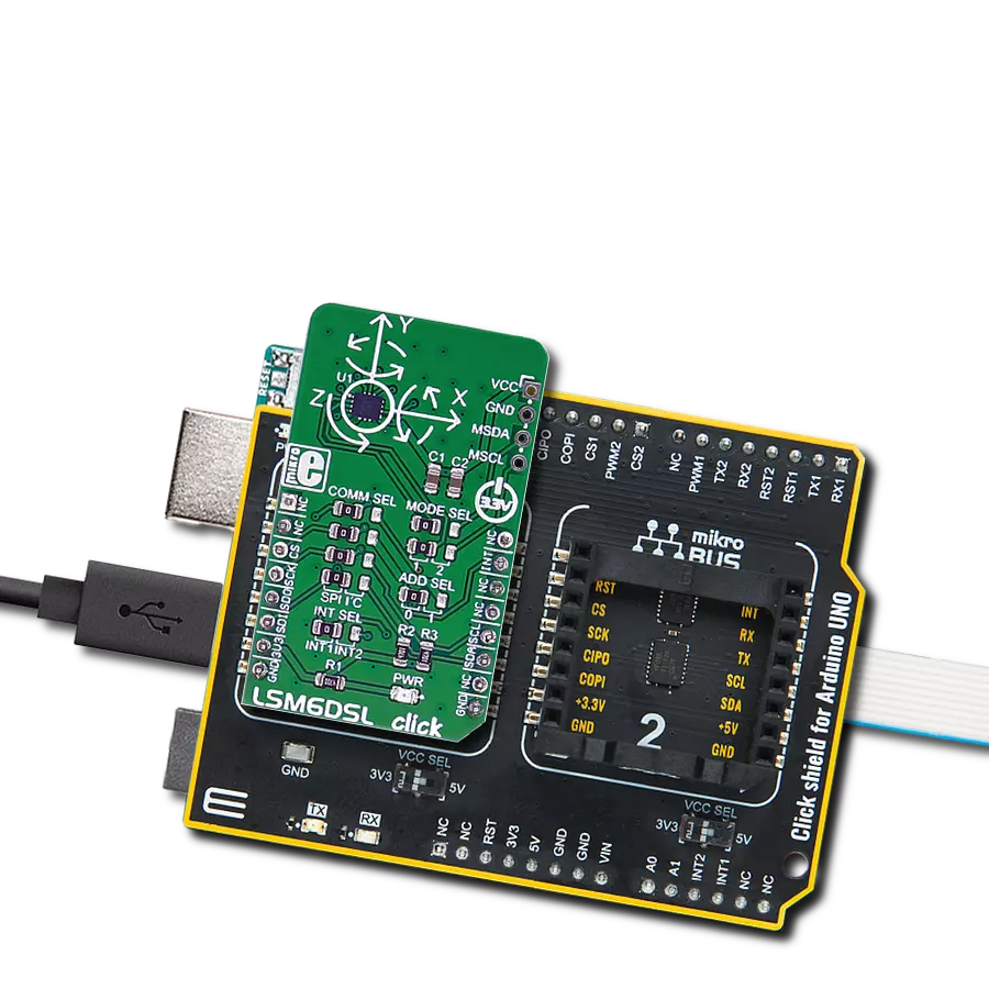
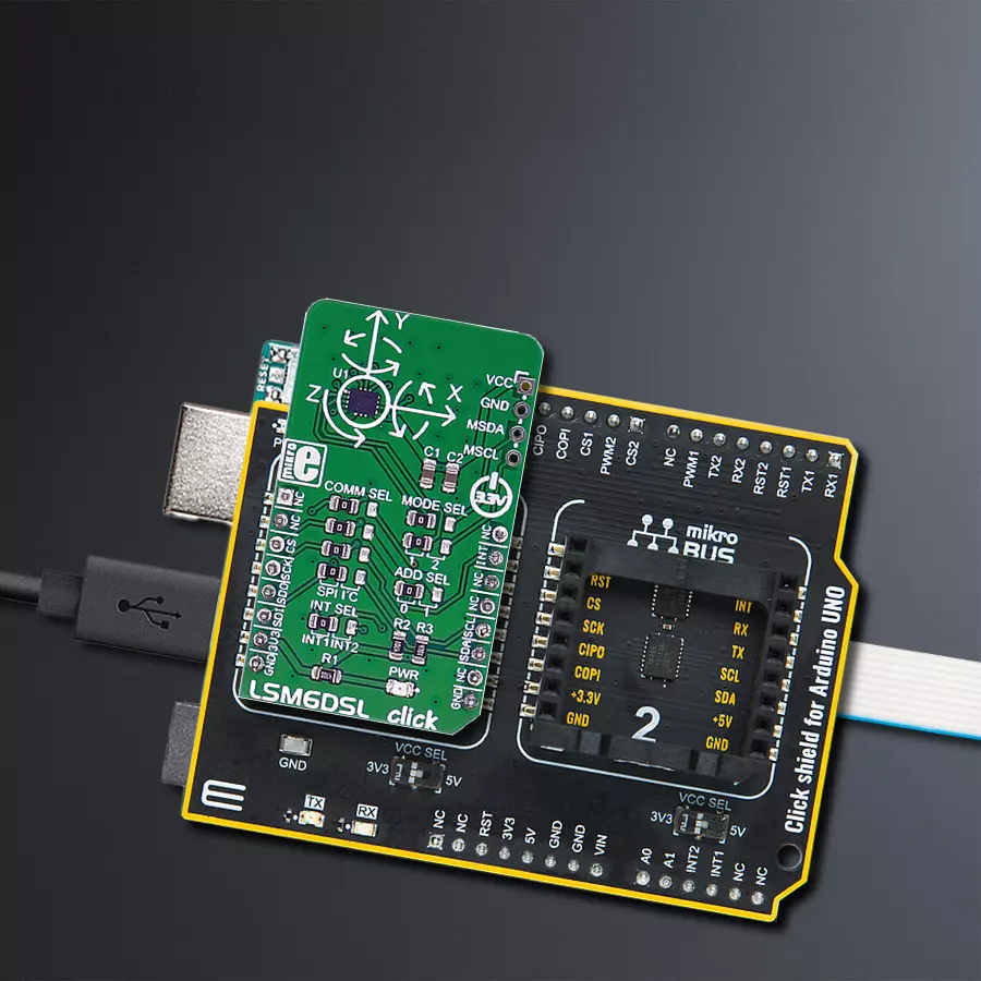
LSM6DSL Click
Dev. board
Arduino UNO Rev3
Compiler
NECTO Studio
MCU
ATmega328P
This solution is a versatile instrument embraced by numerous industries, valued for its precision in capturing motion data and enhancing functions, including navigation, tracking, and control
A
A
Hardware Overview
How does it work?
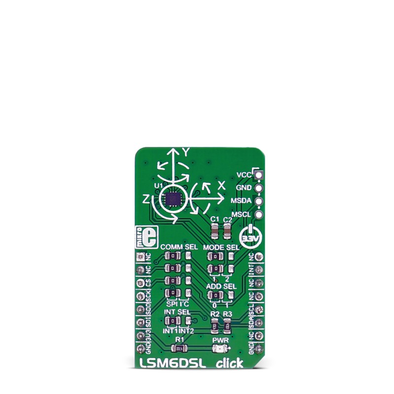
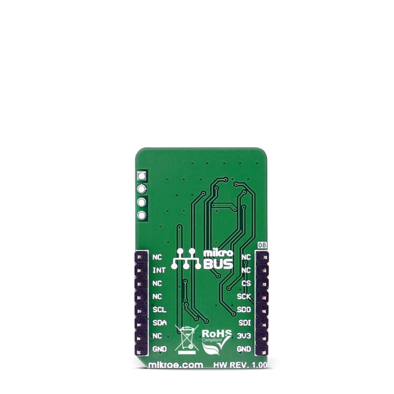
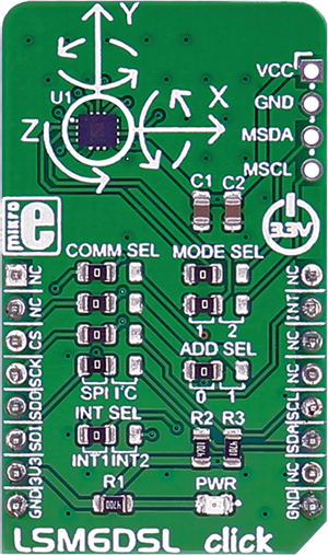
LSM6DSL Click is based on the LSM6DSL, a high-performance 3-axis digital accelerometer and 3-axis digital gyroscope from STMicroelectronics. The click is designed to run on a 3.3V power supply. LSM6DSL click communicates with the target microcontroller over SPI or I2C interface, with additional functionality provided by the INT pin on the mikroBUS™ line. The LSM6DSL is a system-in-package featuring a 3D digital accelerometer and a 3D digital gyroscope
performing at 0.65 mA in high-performance mode, enabling always-on low-power features for an optimal motion experience. The event-detection interrupts enable efficient and reliable motion tracking and contextual awareness, implementing hardware recognition of free-fall events, 6D orientation, click and double-click sensing, activity or inactivity, and wake-up events. The LSM6DSL has a full-scale acceleration range of ±2/±4/±8/±16 g and an angular rate range of
±125/±245/±500/±1000/±2000 dps (degrees per second). This Click board™ can be operated only with a 3.3V logic voltage level. The board must perform appropriate logic voltage level conversion before using MCUs with different logic levels. Also, it comes equipped with a library containing functions and an example code that can be used as a reference for further development.
Features overview
Development board
Arduino UNO is a versatile microcontroller board built around the ATmega328P chip. It offers extensive connectivity options for various projects, featuring 14 digital input/output pins, six of which are PWM-capable, along with six analog inputs. Its core components include a 16MHz ceramic resonator, a USB connection, a power jack, an
ICSP header, and a reset button, providing everything necessary to power and program the board. The Uno is ready to go, whether connected to a computer via USB or powered by an AC-to-DC adapter or battery. As the first USB Arduino board, it serves as the benchmark for the Arduino platform, with "Uno" symbolizing its status as the
first in a series. This name choice, meaning "one" in Italian, commemorates the launch of Arduino Software (IDE) 1.0. Initially introduced alongside version 1.0 of the Arduino Software (IDE), the Uno has since become the foundational model for subsequent Arduino releases, embodying the platform's evolution.

Microcontroller Overview
MCU Card / MCU

Architecture
AVR
MCU Memory (KB)
32
Silicon Vendor
Microchip
Pin count
28
RAM (Bytes)
2048
You complete me!
Accessories
Click Shield for Arduino UNO has two proprietary mikroBUS™ sockets, allowing all the Click board™ devices to be interfaced with the Arduino UNO board without effort. The Arduino Uno, a microcontroller board based on the ATmega328P, provides an affordable and flexible way for users to try out new concepts and build prototypes with the ATmega328P microcontroller from various combinations of performance, power consumption, and features. The Arduino Uno has 14 digital input/output pins (of which six can be used as PWM outputs), six analog inputs, a 16 MHz ceramic resonator (CSTCE16M0V53-R0), a USB connection, a power jack, an ICSP header, and reset button. Most of the ATmega328P microcontroller pins are brought to the IO pins on the left and right edge of the board, which are then connected to two existing mikroBUS™ sockets. This Click Shield also has several switches that perform functions such as selecting the logic levels of analog signals on mikroBUS™ sockets and selecting logic voltage levels of the mikroBUS™ sockets themselves. Besides, the user is offered the possibility of using any Click board™ with the help of existing bidirectional level-shifting voltage translators, regardless of whether the Click board™ operates at a 3.3V or 5V logic voltage level. Once you connect the Arduino UNO board with our Click Shield for Arduino UNO, you can access hundreds of Click boards™, working with 3.3V or 5V logic voltage levels.

Used MCU Pins
mikroBUS™ mapper
Take a closer look
Click board™ Schematic

Step by step
Project assembly

Start by selecting your development board and Click board™. Begin with the Arduino UNO Rev3 as your development board.


Track your results in real time
Application Output
1. Application Output - In Debug mode, the 'Application Output' window enables real-time data monitoring, offering direct insight into execution results. Ensure proper data display by configuring the environment correctly using the provided tutorial.

2. UART Terminal - Use the UART Terminal to monitor data transmission via a USB to UART converter, allowing direct communication between the Click board™ and your development system. Configure the baud rate and other serial settings according to your project's requirements to ensure proper functionality. For step-by-step setup instructions, refer to the provided tutorial.

3. Plot Output - The Plot feature offers a powerful way to visualize real-time sensor data, enabling trend analysis, debugging, and comparison of multiple data points. To set it up correctly, follow the provided tutorial, which includes a step-by-step example of using the Plot feature to display Click board™ readings. To use the Plot feature in your code, use the function: plot(*insert_graph_name*, variable_name);. This is a general format, and it is up to the user to replace 'insert_graph_name' with the actual graph name and 'variable_name' with the parameter to be displayed.

Software Support
Library Description
This library contains API for LSM6DSL Click driver.
Key functions:
lsm6dsl_set_accel_config- This function set accel configuration to the target LSM6DSL_CTRL1_XL register of LSM6DSL sensorlsm6dsl_set_gyro_config- This function set gyro configuration to the target LSM6DSL_CTRL1_XL register of LSM6DSL sensorlsm6dsl_get_axis- This function get axis value from the two target 8-bit register address of LSM6DSL sensor
Open Source
Code example
The complete application code and a ready-to-use project are available through the NECTO Studio Package Manager for direct installation in the NECTO Studio. The application code can also be found on the MIKROE GitHub account.
/*!
 * \file
 * \brief Lsm6Dsl Click example
 *
 * # Description
 * This app measures linear and angular velocity with six degrees of freedom.
 *
 * The demo application is composed of two sections :
 *
 * ## Application Init
 * Initialization driver.
 *
 * ## Application Task
 * This is a example which demonstrates the use of LSM6DSL Click board.
 * LSM6DSL Click communicates with register via SPI by write to register and read from register,
 * measured acceleration and gyroscope coordinates values ( X,Y,Z )
 * Result are being sent to the uart where you can track their changes.
 * All data logs on usb uart for aproximetly every 3 sec.
 *
 * \author MikroE Team
 *
 */
// ------------------------------------------------------------------- INCLUDES

#include "board.h"
#include "log.h"
#include "lsm6dsl.h"

// ------------------------------------------------------------------ VARIABLES

static lsm6dsl_t lsm6dsl;
static log_t logger;
static lsm6dsl_accel_t accel;
static lsm6dsl_gyro_t gyro;

// ------------------------------------------------------ APPLICATION FUNCTIONS

void application_init ( void )
{
    log_cfg_t log_cfg;
    lsm6dsl_cfg_t cfg;

    /**
     * Logger initialization.
     * Default baud rate: 115200
     * Default log level: LOG_LEVEL_DEBUG
     * @note If USB_UART_RX and USB_UART_TX
     * are defined as HAL_PIN_NC, you will
     * need to define them manually for log to work.
     * See @b LOG_MAP_USB_UART macro definition for detailed explanation.
     */
    LOG_MAP_USB_UART( log_cfg );
    log_init( &logger, &log_cfg );
    log_info( &logger, "---- Application Init ----" );

    //  Click initialization.

    lsm6dsl_cfg_setup( &cfg );
    LSM6DSL_MAP_MIKROBUS( cfg, MIKROBUS_1 );
    lsm6dsl_init( &lsm6dsl, &cfg );

    lsm6dsl_default_cfg( &lsm6dsl );

    log_printf( &logger, "---------------------------------------\r\n" );
    log_printf( &logger, "|            LSM6DSL Click            |\r\n" );
    log_printf( &logger, "---------------------------------------\r\n" );
    log_printf( &logger, "|     Accel       |       Gyro        |\r\n" );
    log_printf( &logger, "---------------------------------------\r\n" );

    Delay_ms ( 100 );
}

void application_task ( void )
{

    lsm6dsl_get_accel( &lsm6dsl, &accel, LSM6DSL_FULLSCALE_XL_2 );

    Delay_ms ( 10 );

    lsm6dsl_get_gyro( &lsm6dsl, &gyro, LSM6DSL_FULLSCALE_G_245 );

    Delay_ms ( 10 );

    log_printf( &logger, " Accel X : %.2f |  Gyro X : %.2f |\r\n", accel.accel_x, gyro.gyro_x );

    log_printf( &logger, " Accel Y : %.2f |  Gyro Y : %.2f |\r\n", accel.accel_y, gyro.gyro_y );

    log_printf( &logger, " Accel Z : %.2f |  Gyro Z : %.2f |\r\n", accel.accel_z, gyro.gyro_z );

    log_printf( &logger, "---------------------------------------\r\n" );

    Delay_ms ( 1000 );
    Delay_ms ( 1000 );
    Delay_ms ( 1000 );
}

int main ( void )
{
    /* Do not remove this line or clock might not be set correctly. */
    #ifdef PREINIT_SUPPORTED
    preinit();
    #endif

    application_init( );

    for ( ; ; )
    {
        application_task( );
    }

    return 0;
}

// ------------------------------------------------------------------------ END
Additional Support
Resources
Category:Motion


