Master voltage regulation with MIC24045 and ATmega328P
Power-on-the-Go

Published Feb 14, 2024
Click board™
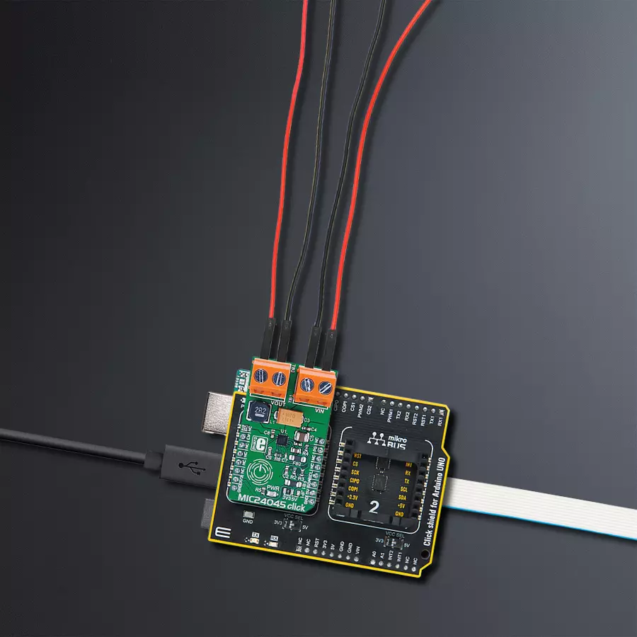
MIC24045 click
Dev. board
Arduino UNO Rev3
Compiler
NECTO Studio
MCU
ATmega328P
Perfect portable power solution that transforms voltage levels with precision to ensure optimal performance for a wide range of electronic devices
A
A
Hardware Overview
How does it work?
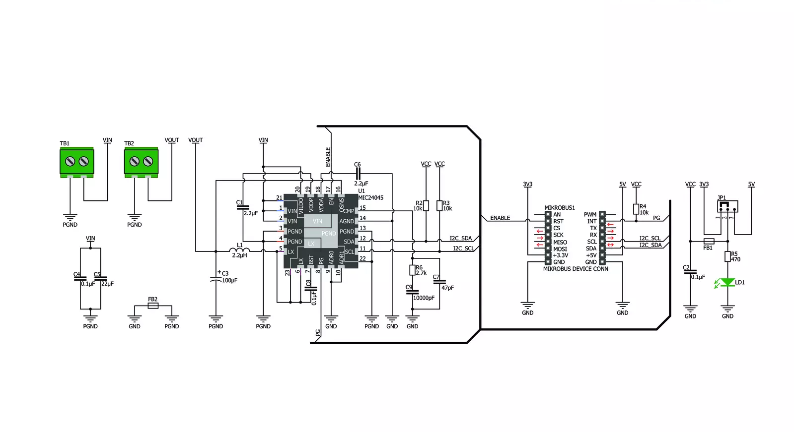
MIC24045 Click is based on the MIC24045, an I2C-programmable, high-efficiency, wide input range, 5A synchronous step-down regulator from Microchip. This Click board™ is designed to run on either 3.3V or 5V power supply. It communicates with the target microcontroller over the I2C interface with additional functionality provided by the following pins on the mikroBUS™ line: RST, INT. The MIC24045 is a digitally programmable, 5A valley current-mode controlled regulator
featuring an input voltage range from 4.5V to 19V. The MIC24045 is ideally suited for multiple voltage rail application environments, typically found in computing and telecommunication systems. The MIC24045 has thermal shutdown protection that prevents operation at excessive temperatures. The MIC24045 features a Thermal Warning flag readable through the I2C interface (register polling is needed). The Thermal Warning flag signals the approach of the thermal shutdown so that
appropriate system-level countermeasures can be undertaken. This Click board™ is designed to lower the voltage on the input from 4.5V-19V to 0.64V-5.25V. The same voltage is used for powering the MCP24045 IC (TB1 and TB2 connectors). The voltage on the mikroBUS™ I2C pin can be either 3.3V or 5V, depending on the jumper position. The selected mikroBUS™ power supply is used only for the pull-ups on I2C lines.

Features overview
Development board
Arduino UNO is a versatile microcontroller board built around the ATmega328P chip. It offers extensive connectivity options for various projects, featuring 14 digital input/output pins, six of which are PWM-capable, along with six analog inputs. Its core components include a 16MHz ceramic resonator, a USB connection, a power jack, an
ICSP header, and a reset button, providing everything necessary to power and program the board. The Uno is ready to go, whether connected to a computer via USB or powered by an AC-to-DC adapter or battery. As the first USB Arduino board, it serves as the benchmark for the Arduino platform, with "Uno" symbolizing its status as the
first in a series. This name choice, meaning "one" in Italian, commemorates the launch of Arduino Software (IDE) 1.0. Initially introduced alongside version 1.0 of the Arduino Software (IDE), the Uno has since become the foundational model for subsequent Arduino releases, embodying the platform's evolution.

Microcontroller Overview
MCU Card / MCU

Architecture
AVR
MCU Memory (KB)
32
Silicon Vendor
Microchip
Pin count
28
RAM (Bytes)
2048
You complete me!
Accessories
Click Shield for Arduino UNO has two proprietary mikroBUS™ sockets, allowing all the Click board™ devices to be interfaced with the Arduino UNO board without effort. The Arduino Uno, a microcontroller board based on the ATmega328P, provides an affordable and flexible way for users to try out new concepts and build prototypes with the ATmega328P microcontroller from various combinations of performance, power consumption, and features. The Arduino Uno has 14 digital input/output pins (of which six can be used as PWM outputs), six analog inputs, a 16 MHz ceramic resonator (CSTCE16M0V53-R0), a USB connection, a power jack, an ICSP header, and reset button. Most of the ATmega328P microcontroller pins are brought to the IO pins on the left and right edge of the board, which are then connected to two existing mikroBUS™ sockets. This Click Shield also has several switches that perform functions such as selecting the logic levels of analog signals on mikroBUS™ sockets and selecting logic voltage levels of the mikroBUS™ sockets themselves. Besides, the user is offered the possibility of using any Click board™ with the help of existing bidirectional level-shifting voltage translators, regardless of whether the Click board™ operates at a 3.3V or 5V logic voltage level. Once you connect the Arduino UNO board with our Click Shield for Arduino UNO, you can access hundreds of Click boards™, working with 3.3V or 5V logic voltage levels.

Used MCU Pins
mikroBUS™ mapper
Take a closer look
Click board™ Schematic
Step by step
Project assembly

Start by selecting your development board and Click board™. Begin with the Arduino UNO Rev3 as your development board.


Track your results in real time
Application Output
1. Application Output - In Debug mode, the 'Application Output' window enables real-time data monitoring, offering direct insight into execution results. Ensure proper data display by configuring the environment correctly using the provided tutorial.

2. UART Terminal - Use the UART Terminal to monitor data transmission via a USB to UART converter, allowing direct communication between the Click board™ and your development system. Configure the baud rate and other serial settings according to your project's requirements to ensure proper functionality. For step-by-step setup instructions, refer to the provided tutorial.

3. Plot Output - The Plot feature offers a powerful way to visualize real-time sensor data, enabling trend analysis, debugging, and comparison of multiple data points. To set it up correctly, follow the provided tutorial, which includes a step-by-step example of using the Plot feature to display Click board™ readings. To use the Plot feature in your code, use the function: plot(*insert_graph_name*, variable_name);. This is a general format, and it is up to the user to replace 'insert_graph_name' with the actual graph name and 'variable_name' with the parameter to be displayed.

Software Support
Library Description
This library contains API for MIC24045 Click driver.
Key functions:
mic24045_get_vout- Get voltagemic24045_set_vout_decimal- Set voltage decimalmic24045_get_status- Get status function
Open Source
Code example
The complete application code and a ready-to-use project are available through the NECTO Studio Package Manager for direct installation in the NECTO Studio. The application code can also be found on the MIKROE GitHub account.
/*!
 * \file
 * \brief Mic24045 Click example
 *
 * # Description
 * This example demonstrates the use of MIC24045 Click board.
 *
 * The demo application is composed of two sections :
 *
 * ## Application Init
 * Initializes the driver and enables the voltage output.
 *
 * ## Application Task
 * Changes the voltage output every 2 seconds and displays the current set value
 * on the USB UART.
 *
 * \author MikroE Team
 *
 */
// ------------------------------------------------------------------- INCLUDES

#include "board.h"
#include "log.h"
#include "mic24045.h"

// ------------------------------------------------------------------ VARIABLES

static mic24045_t mic24045;
static log_t logger;
static float current_voltage;

// ------------------------------------------------------ APPLICATION FUNCTIONS

void application_init ( void )
{
    log_cfg_t log_cfg;
    mic24045_cfg_t cfg;

    /**
     * Logger initialization.
     * Default baud rate: 115200
     * Default log level: LOG_LEVEL_DEBUG
     * @note If USB_UART_RX and USB_UART_TX
     * are defined as HAL_PIN_NC, you will
     * need to define them manually for log to work.
     * See @b LOG_MAP_USB_UART macro definition for detailed explanation.
     */
    LOG_MAP_USB_UART( log_cfg );
    log_init( &logger, &log_cfg );
    log_info( &logger, "---- Application Init ----" );

    //  Click initialization.

    mic24045_cfg_setup( &cfg );
    MIC24045_MAP_MIKROBUS( cfg, MIKROBUS_1 );
    mic24045_init( &mic24045, &cfg );

    mic24045_enable( &mic24045 );
    log_printf( &logger, " Output enabled!\r\n" );
    Delay_ms ( 100 );
}

void application_task ( void )
{
    for ( uint16_t cnt = MIC24045_MIN_VOUT_DEC; cnt <= MIC24045_MAX_VOUT_DEC; cnt += 15 )
    {
        mic24045_set_vout_decimal( &mic24045, cnt );
        Delay_ms ( 500 );
        current_voltage = mic24045_get_vout( &mic24045 );

        log_printf( &logger, " VOUT:    ~%.3f V\r\n", current_voltage );
        log_printf( &logger, "------------------\r\n" );
        Delay_ms ( 1000 );
        Delay_ms ( 500 );
    }
}

int main ( void )
{
    /* Do not remove this line or clock might not be set correctly. */
    #ifdef PREINIT_SUPPORTED
    preinit();
    #endif

    application_init( );

    for ( ; ; )
    {
        application_task( );
    }

    return 0;
}


// ------------------------------------------------------------------------ END
Additional Support
Resources
Category:Buck


