Ensure your energy is transformed with minimal loss thanks to RPL-3.0-R and ATmega328
The epitome of voltage control

Published Feb 14, 2024
Click board™
Nano Power 3 Click
Dev. board
Arduino UNO Rev3
Compiler
NECTO Studio
MCU
ATmega328
Our outstanding buck converter solution, the pocket-sized powerhouse, transforms voltage seamlessly, providing a reliable and efficient energy source for your projects.
A
A
Hardware Overview
How does it work?
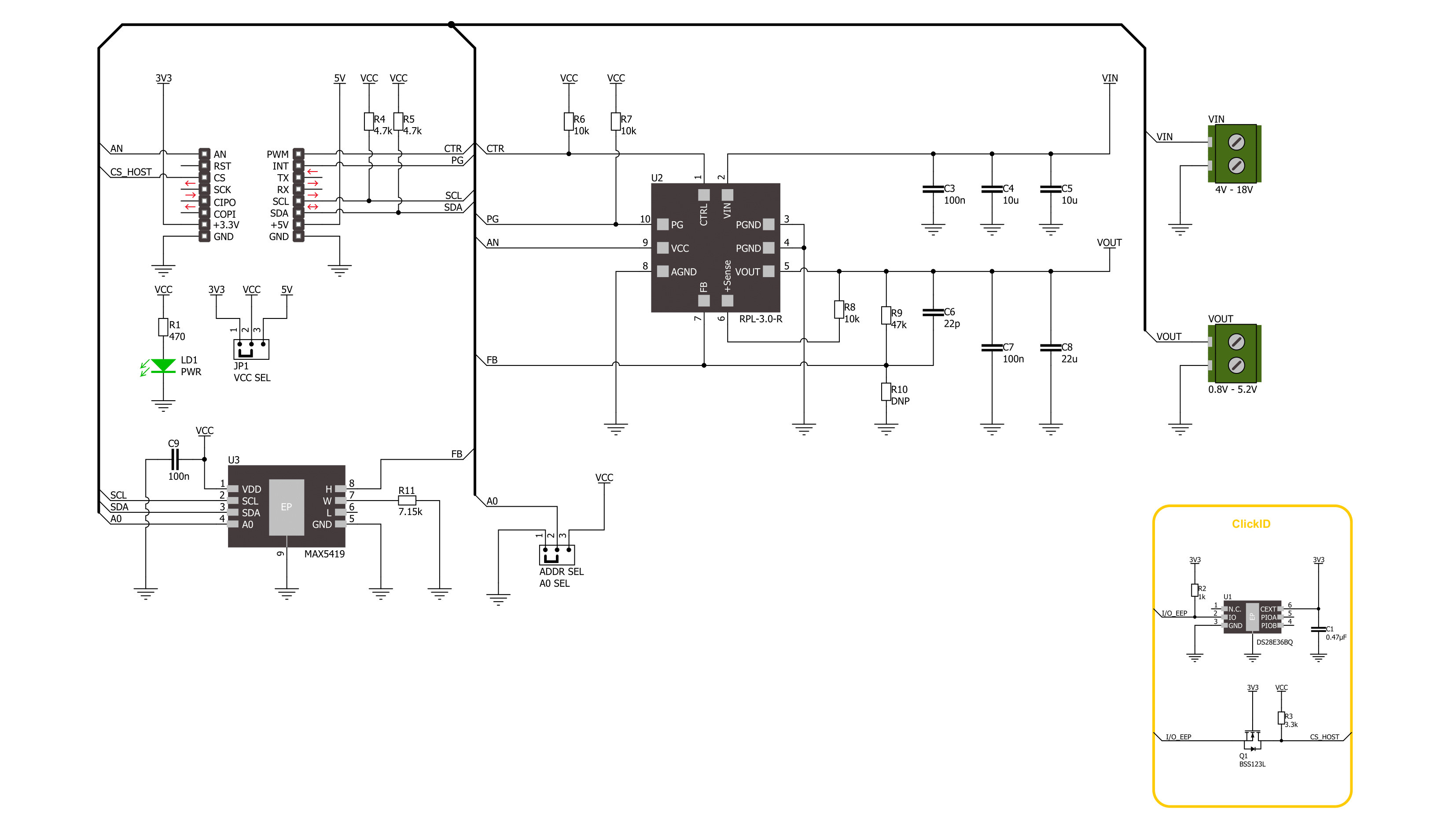
Nano Power 3 Click is based on the RPL-3.0-R, a buck converter with an integrated inductor from Recom Power. This thermally-enhanced converter uses, as input, voltage from 4 up to 18VDC, thus allowing 5V and 12V supply rails to be used. It's fully protected against continuous short circuits, output overcurrent, or over-temperature faults. To set the output voltage on the VOUT terminal, the Nano Power 3 Click uses the MAX5419, a 256-tap nonvolatile digital potentiometer from Analog Devices. This potentiometer features the power-on recall of the wiper position from nonvolatile EEPROM memory. The nominal resistance of this
potentiometer is 200kΩ, and with an onboard resistor, it makes a voltage divider that feeds the feedback input of the buck converter. You select the output voltage value by setting the resistance value on this potentiometer. Nano Power 3 Click uses a standard 2-Wire I2C interface of the MAX5419 to communicate with the host MCU, supporting Fast mode and data rates of up to 400Kbps. The I2C address can be set over the ADDR SEL jumper with 0 selected by default. In addition to the digital potentiometer control, you can also control the buck converter by turning it OFF via the CTR pin. The PG pin serves as the buck
converter Power Good condition output, which interrupts the host MCU according to meeting one of the overvoltage or undervoltage thresholds and sink current capability. The buck converter's output voltage can be read over the AN pin of the mikroBUS™ socket. This Click board™ can operate with either 3.3V or 5V logic voltage levels selected via the VCC SEL jumper. This way, both 3.3V and 5V capable MCUs can use the communication lines properly. Also, this Click board™ comes equipped with a library containing easy-to-use functions and an example code that can be used as a reference for further development.

Features overview
Development board
Arduino UNO is a versatile microcontroller board built around the ATmega328P chip. It offers extensive connectivity options for various projects, featuring 14 digital input/output pins, six of which are PWM-capable, along with six analog inputs. Its core components include a 16MHz ceramic resonator, a USB connection, a power jack, an
ICSP header, and a reset button, providing everything necessary to power and program the board. The Uno is ready to go, whether connected to a computer via USB or powered by an AC-to-DC adapter or battery. As the first USB Arduino board, it serves as the benchmark for the Arduino platform, with "Uno" symbolizing its status as the
first in a series. This name choice, meaning "one" in Italian, commemorates the launch of Arduino Software (IDE) 1.0. Initially introduced alongside version 1.0 of the Arduino Software (IDE), the Uno has since become the foundational model for subsequent Arduino releases, embodying the platform's evolution.

Microcontroller Overview
MCU Card / MCU

Architecture
AVR
MCU Memory (KB)
32
Silicon Vendor
Microchip
Pin count
32
RAM (Bytes)
2048
You complete me!
Accessories
Click Shield for Arduino UNO has two proprietary mikroBUS™ sockets, allowing all the Click board™ devices to be interfaced with the Arduino UNO board without effort. The Arduino Uno, a microcontroller board based on the ATmega328P, provides an affordable and flexible way for users to try out new concepts and build prototypes with the ATmega328P microcontroller from various combinations of performance, power consumption, and features. The Arduino Uno has 14 digital input/output pins (of which six can be used as PWM outputs), six analog inputs, a 16 MHz ceramic resonator (CSTCE16M0V53-R0), a USB connection, a power jack, an ICSP header, and reset button. Most of the ATmega328P microcontroller pins are brought to the IO pins on the left and right edge of the board, which are then connected to two existing mikroBUS™ sockets. This Click Shield also has several switches that perform functions such as selecting the logic levels of analog signals on mikroBUS™ sockets and selecting logic voltage levels of the mikroBUS™ sockets themselves. Besides, the user is offered the possibility of using any Click board™ with the help of existing bidirectional level-shifting voltage translators, regardless of whether the Click board™ operates at a 3.3V or 5V logic voltage level. Once you connect the Arduino UNO board with our Click Shield for Arduino UNO, you can access hundreds of Click boards™, working with 3.3V or 5V logic voltage levels.

Used MCU Pins
mikroBUS™ mapper
Take a closer look
Click board™ Schematic
Step by step
Project assembly

Start by selecting your development board and Click board™. Begin with the Arduino UNO Rev3 as your development board.


Track your results in real time
Application Output
1. Application Output - In Debug mode, the 'Application Output' window enables real-time data monitoring, offering direct insight into execution results. Ensure proper data display by configuring the environment correctly using the provided tutorial.

2. UART Terminal - Use the UART Terminal to monitor data transmission via a USB to UART converter, allowing direct communication between the Click board™ and your development system. Configure the baud rate and other serial settings according to your project's requirements to ensure proper functionality. For step-by-step setup instructions, refer to the provided tutorial.

3. Plot Output - The Plot feature offers a powerful way to visualize real-time sensor data, enabling trend analysis, debugging, and comparison of multiple data points. To set it up correctly, follow the provided tutorial, which includes a step-by-step example of using the Plot feature to display Click board™ readings. To use the Plot feature in your code, use the function: plot(*insert_graph_name*, variable_name);. This is a general format, and it is up to the user to replace 'insert_graph_name' with the actual graph name and 'variable_name' with the parameter to be displayed.

Software Support
Library Description
This library contains API for Nano Power 3 Click driver.
Key functions:
nanopower3_set_ctr_pin- Nano Power 3 set CTRL pin state function.nanopower3_set_wiper_pos- Nano Power 3 set wiper position function.nanopower3_set_voltage- Nano Power 3 set output voltage function.
Open Source
Code example
The complete application code and a ready-to-use project are available through the NECTO Studio Package Manager for direct installation in the NECTO Studio. The application code can also be found on the MIKROE GitHub account.
/*!
 * @file main.c
 * @brief Nano Power 3 Click example
 *
 * # Description
 * This library contains API for the Nano Power 3 Click driver.
 * This driver provides the functions to set the output voltage treshold.
 *
 * The demo application is composed of two sections :
 *
 * ## Application Init
 * Initialization of I2C module and log UART.
 * After driver initialization, default settings sets output voltage to 1 V.
 *
 * ## Application Task
 * This example demonstrates the use of the Nano Power 3 Click board™ by changing
 * output voltage every 5 seconds starting from 1 V up to 4.5 V.
 *
 * @author Stefan Ilic
 *
 */

#include "board.h"
#include "log.h"
#include "nanopower3.h"

static nanopower3_t nanopower3;
static log_t logger;

/**
 * @brief Output level printing function.
 * @details This function is used to log value of the selected voltage to UART terminal.
 * @param[in] sel_level : Selected voltage level.
 * @return Nothing.
 * @note None.
 */
static void print_selected_output_level ( uint8_t sel_level );

void application_init ( void )
{
    log_cfg_t log_cfg;  /**< Logger config object. */
    nanopower3_cfg_t nanopower3_cfg;  /**< Click config object. */

    /**
     * Logger initialization.
     * Default baud rate: 115200
     * Default log level: LOG_LEVEL_DEBUG
     * @note If USB_UART_RX and USB_UART_TX
     * are defined as HAL_PIN_NC, you will
     * need to define them manually for log to work.
     * See @b LOG_MAP_USB_UART macro definition for detailed explanation.
     */
    LOG_MAP_USB_UART( log_cfg );
    log_init( &logger, &log_cfg );
    log_info( &logger, " Application Init " );

    // Click initialization.
    nanopower3_cfg_setup( &nanopower3_cfg );
    NANOPOWER3_MAP_MIKROBUS( nanopower3_cfg, MIKROBUS_1 );
    if ( I2C_MASTER_ERROR == nanopower3_init( &nanopower3, &nanopower3_cfg ) )
    {
        log_error( &logger, " Communication init." );
        for ( ; ; );
    }

    if ( NANOPOWER3_ERROR == nanopower3_default_cfg ( &nanopower3 ) )
    {
        log_error( &logger, " Default configuration." );
        for ( ; ; );
    }

    log_info( &logger, " Application Task " );
}

void application_task ( void )
{
    for ( uint8_t n_cnt = NANOPOWER3_1V_OUT_VOLTAGE; n_cnt <= NANOPOWER3_4V5_OUT_VOLTAGE; n_cnt++ )
    {
        nanopower3_set_voltage( &nanopower3, n_cnt );
        log_printf( &logger, " Selected output is:" );
        print_selected_output_level ( n_cnt );
        Delay_ms ( 1000 );
        Delay_ms ( 1000 );
        Delay_ms ( 1000 );
        Delay_ms ( 1000 );
        Delay_ms ( 1000 );
    }
}

int main ( void )
{
    /* Do not remove this line or clock might not be set correctly. */
    #ifdef PREINIT_SUPPORTED
    preinit();
    #endif

    application_init( );

    for ( ; ; )
    {
        application_task( );
    }

    return 0;
}

static void print_selected_output_level ( uint8_t sel_level )
{
    switch ( sel_level )
    {
        case ( NANOPOWER3_1V_OUT_VOLTAGE ):
        {
            log_printf( &logger, " 1V\r\n" );
            break;
        }
        case ( NANOPOWER3_1V2_OUT_VOLTAGE ):
        {
            log_printf( &logger, " 1.2V\r\n" );
            break;
        }
        case ( NANOPOWER3_1V5_OUT_VOLTAGE ):
        {
            log_printf( &logger, " 1.5V\r\n" );
            break;
        }
        case ( NANOPOWER3_1V8_OUT_VOLTAGE ):
        {
            log_printf( &logger, " 1.8V\r\n" );
            break;
        }
        case ( NANOPOWER3_2V_OUT_VOLTAGE ):
        {
            log_printf( &logger, " 2V\r\n" );
            break;
        }
        case ( NANOPOWER3_2V5_OUT_VOLTAGE ):
        {
            log_printf( &logger, " 2.5V\r\n" );
            break;
        }
        case ( NANOPOWER3_3V_OUT_VOLTAGE ):
        {
            log_printf( &logger, " 3V\r\n" );
            break;
        }
        case ( NANOPOWER3_3V3_OUT_VOLTAGE ):
        {
            log_printf( &logger, " 3.3V\r\n" );
            break;
        }
        case ( NANOPOWER3_3V5_OUT_VOLTAGE ):
        {
            log_printf( &logger, " 3.5V\r\n" );
            break;
        }
        case ( NANOPOWER3_4V_OUT_VOLTAGE ):
        {
            log_printf( &logger, " 4V\r\n" );
            break;
        }
        case ( NANOPOWER3_4V5_OUT_VOLTAGE ):
        {
            log_printf( &logger, " 4.5V\r\n" );
            break;
        }
        default:
        {
            log_printf( &logger, " ERROR\r\n" );
        }
    }
}

// ------------------------------------------------------------------------ END
Additional Support
Resources
Category:Buck


