Enhance your industrial processes with ADS1247 and ATmega328P
RTDs - The path to temperature excellence
Published Feb 14, 2024
Click board™
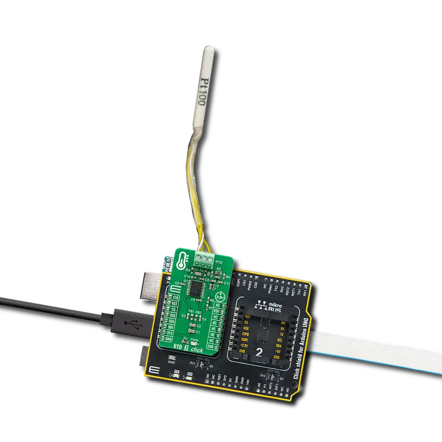
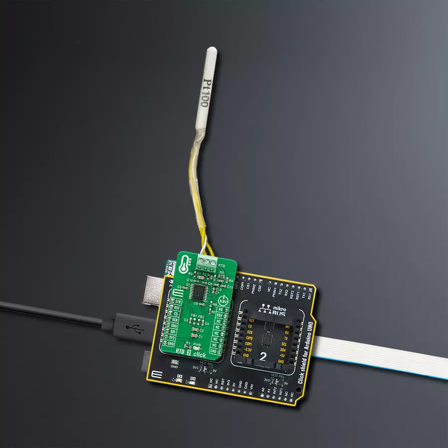
RTD 2 Click
Dev. board
Arduino UNO Rev3
Compiler
NECTO Studio
MCU
ATmega328P
Discover how our RTD solution can provide you with accurate and reliable temperature measurements for your critical processes.
A
A
Hardware Overview
How does it work?
RTD 2 Click is based on the ADS1247, a highly integrated 24-bit data converter with a programmable gain amplifier (PGA) for sensor measurement applications from Texas Instruments. The ADS1247 includes a delta-sigma (ΔΣ) ADC with an adjustable single-cycle settling digital filter, an internal oscillator, and an SPI-compatible serial interface. It also has a flexible input multiplexer with system monitoring capability and general-purpose I/O settings, a very low-drift voltage reference, and two matched current sources for sensor excitation. The ADS1247 provides a system monitor function. This function can measure the analog power supply, digital power supply, external voltage reference, or ambient temperature. Note that the system monitor function provides a coarse result. When the system monitor is enabled, the analog inputs are disconnected. The two IDAC current sources integrated into the ADS1247 are used to implement the lead-wire compensation. One IDAC current source (IDAC1) provides excitation to the RTD element. The other current source (IDAC2)
has the same current setting, which cancels lead-wire resistance by generating a voltage drop across lead-wire resistance R2 equal to the voltage drop across the R1 resistor (9.09k). Because the voltage across the RTD is measured differentially at ADC pins AIN1 and AIN2 of the ADS1247, the voltages across the lead-wire resistances cancel. The ADC reference voltage (pins REFP0 and REFN0) is derived from the voltage across the R5 resistor with the currents from IDAC1 and IDAC2, providing ratiometric cancellation of current-source drift. R5 also level shifts the RTD signal to within the ADC-specified common-mode input range. The RTD 2 Click communicates with MCU using the standard SPI serial interface with an additional data-ready signal routed on the INT pin of the mikroBUS™ socket labeled as RDY. Data Ready signal indicates when a new conversion is complete, and the conversion result is stored in the conversion result buffer. It also has an active-low Reset signal routed on the RST pin of the mikroBUS™ used to reset the device and a precise conversion control signal routed on the AN pin of
the mikroBUS™ socket labeled as STR. The ADS1247 stays in Reset Mode as long as the RST pin stays low. When the RST pin goes high, the ADC comes out of Reset Mode and can convert data. This Click board™ can work only with 3-wire probe types that MIKROE offers, such as the PT100 type Platinum Probe, an RTD probe used to measure temperatures up to 250°C. Platinum is an excellent choice since they are very stable and reusable and are resistant to corrosion or oxidation. The measurement probe is connected to the RTD 2 Click by using the screw terminal on the top of the board, and it has wires that can be 1m long, which makes it possible to measure high temperatures from a safe distance. This Click board™ can be operated only with a 3.3V logic voltage level. The board must perform appropriate logic voltage level conversion before using MCUs with different logic levels. Also, it comes equipped with a library containing functions and an example code that can be used as a reference for further development.

Features overview
Development board
Arduino UNO is a versatile microcontroller board built around the ATmega328P chip. It offers extensive connectivity options for various projects, featuring 14 digital input/output pins, six of which are PWM-capable, along with six analog inputs. Its core components include a 16MHz ceramic resonator, a USB connection, a power jack, an
ICSP header, and a reset button, providing everything necessary to power and program the board. The Uno is ready to go, whether connected to a computer via USB or powered by an AC-to-DC adapter or battery. As the first USB Arduino board, it serves as the benchmark for the Arduino platform, with "Uno" symbolizing its status as the
first in a series. This name choice, meaning "one" in Italian, commemorates the launch of Arduino Software (IDE) 1.0. Initially introduced alongside version 1.0 of the Arduino Software (IDE), the Uno has since become the foundational model for subsequent Arduino releases, embodying the platform's evolution.

Microcontroller Overview
MCU Card / MCU

Architecture
AVR
MCU Memory (KB)
32
Silicon Vendor
Microchip
Pin count
28
RAM (Bytes)
2048
You complete me!
Accessories
Click Shield for Arduino UNO has two proprietary mikroBUS™ sockets, allowing all the Click board™ devices to be interfaced with the Arduino UNO board without effort. The Arduino Uno, a microcontroller board based on the ATmega328P, provides an affordable and flexible way for users to try out new concepts and build prototypes with the ATmega328P microcontroller from various combinations of performance, power consumption, and features. The Arduino Uno has 14 digital input/output pins (of which six can be used as PWM outputs), six analog inputs, a 16 MHz ceramic resonator (CSTCE16M0V53-R0), a USB connection, a power jack, an ICSP header, and reset button. Most of the ATmega328P microcontroller pins are brought to the IO pins on the left and right edge of the board, which are then connected to two existing mikroBUS™ sockets. This Click Shield also has several switches that perform functions such as selecting the logic levels of analog signals on mikroBUS™ sockets and selecting logic voltage levels of the mikroBUS™ sockets themselves. Besides, the user is offered the possibility of using any Click board™ with the help of existing bidirectional level-shifting voltage translators, regardless of whether the Click board™ operates at a 3.3V or 5V logic voltage level. Once you connect the Arduino UNO board with our Click Shield for Arduino UNO, you can access hundreds of Click boards™, working with 3.3V or 5V logic voltage levels.

The PT100 3-wire temperature probe is an advanced RTD platinum sensor designed for precise temperature measurement up to 250°C. Perfectly compatible with the RTD Click board™, this probe utilizes RTD sensors - thermosensitive resistors that adapt their resistance to temperature changes. The probe's core features a meticulously crafted strip of platinum with a resistance of 100Ω at 0°C, earning the designation PT100. Key features include a temperature range of up to 250⁰ Celsius, a 3-wire configuration for enhanced accuracy, a length of 1m (100cm, 3.37 inches), Grade 2B construction for durability, and a tight tolerance of 0.5". Whether in industrial or scientific settings, the PT100 3-wire temperature probe delivers reliable and precise temperature readings, ensuring optimal performance in diverse applications.

Used MCU Pins
mikroBUS™ mapper
Take a closer look
Click board™ Schematic

Step by step
Project assembly

Start by selecting your development board and Click board™. Begin with the Arduino UNO Rev3 as your development board.


Track your results in real time
Application Output
1. Application Output - In Debug mode, the 'Application Output' window enables real-time data monitoring, offering direct insight into execution results. Ensure proper data display by configuring the environment correctly using the provided tutorial.

2. UART Terminal - Use the UART Terminal to monitor data transmission via a USB to UART converter, allowing direct communication between the Click board™ and your development system. Configure the baud rate and other serial settings according to your project's requirements to ensure proper functionality. For step-by-step setup instructions, refer to the provided tutorial.

3. Plot Output - The Plot feature offers a powerful way to visualize real-time sensor data, enabling trend analysis, debugging, and comparison of multiple data points. To set it up correctly, follow the provided tutorial, which includes a step-by-step example of using the Plot feature to display Click board™ readings. To use the Plot feature in your code, use the function: plot(*insert_graph_name*, variable_name);. This is a general format, and it is up to the user to replace 'insert_graph_name' with the actual graph name and 'variable_name' with the parameter to be displayed.

Software Support
Library Description
This library contains API for RTD 2 Click driver.
Key functions:
rtd2_check_new_data_ready- The function check new data readyrtd2_get_temperature- The function read output data and return ambient temperature from the PT100 3-wire temperature probertd2_enable_start- The function enables ADC conversion
Open Source
Code example
The complete application code and a ready-to-use project are available through the NECTO Studio Package Manager for direct installation in the NECTO Studio. The application code can also be found on the MIKROE GitHub account.
/*!
 * \file
 * \brief Rtd 2 Click example
 *
 * # Description
 * RTD 2 Click board is commonly used for measuring ambient temperature
 * from the PT100 3-wire temperature probe.
 *
 * The demo application is composed of two sections :
 *
 * ## Application Init
 * Initializes the driver, performs a hardware reset, and sets the Click
 * default configuration.
 *
 * ## Application Task
 * Reads an ambient temperature measured by the PT100 3-wire temperature probe
 * connected to the RTD 2 Click board, and logs the results on the USB UART each second.
 *
 * \author MikroE Team
 *
 */
// ------------------------------------------------------------------- INCLUDES

#include "board.h"
#include "log.h"
#include "rtd2.h"

// ------------------------------------------------------------------ VARIABLES

static rtd2_t rtd2;
static log_t logger;
static float temperature;

// ------------------------------------------------------ APPLICATION FUNCTIONS

void application_init ( void )
{
    log_cfg_t log_cfg;
    rtd2_cfg_t cfg;

    /**
     * Logger initialization.
     * Default baud rate: 115200
     * Default log level: LOG_LEVEL_DEBUG
     * @note If USB_UART_RX and USB_UART_TX
     * are defined as HAL_PIN_NC, you will
     * need to define them manually for log to work.
     * See @b LOG_MAP_USB_UART macro definition for detailed explanation.
     */
    LOG_MAP_USB_UART( log_cfg );
    log_init( &logger, &log_cfg );
    log_info( &logger, "---- Application Init ----" );

    //  Click initialization.
    rtd2_cfg_setup( &cfg );
    RTD2_MAP_MIKROBUS( cfg, MIKROBUS_1 );
    rtd2_init( &rtd2, &cfg );
    Delay_ms ( 200 );

    log_printf( &logger, "----- Hardware Reset ------\r\n" );
    rtd2_hw_reset( &rtd2 );
    Delay_ms ( 100 );

    log_printf( &logger, "-- Default configuration --\r\n" );
    rtd2_default_cfg( &rtd2 );
    Delay_ms ( 1000 );

    log_printf( &logger, "--------------------------\r\n" );
    log_printf( &logger, "     Start Measurement    \r\n" );
    log_printf( &logger, "--------------------------\r\n" );
    Delay_ms ( 100 );
}

void application_task ( void )
{
    if ( rtd2_check_new_data_ready( &rtd2 ) == RTD2_NEW_DATA_IS_READY )
    {
        temperature = rtd2_get_temperature( &rtd2 );
        log_printf( &logger, " Temperature : %.2f C\r\n", temperature );
        log_printf( &logger, "--------------------------\r\n");
        Delay_ms ( 1000 );
    }
    else
    {
        rtd2_enable_start( &rtd2, RTD2_START_CONVERSION_DISABLE );
        Delay_ms ( 1000 );
    }
}

int main ( void )
{
    /* Do not remove this line or clock might not be set correctly. */
    #ifdef PREINIT_SUPPORTED
    preinit();
    #endif

    application_init( );

    for ( ; ; )
    {
        application_task( );
    }

    return 0;
}


// ------------------------------------------------------------------------ END
Additional Support
Resources
Category:Temperature & humidity


