Enable smooth and silent operation of connected stepper motors with TMC2130 and ATmega328P
Two-phase bipolar stepper motor driver with StealthChop™ for quiet movement

Published Feb 14, 2024
Click board™
Silent Step 2 Click
Dev. board
Arduino UNO Rev3
Compiler
NECTO Studio
MCU
ATmega328P
A compact and efficient solution for achieving smooth, silent, and precise motor control in diverse industrial applications
A
A
Hardware Overview
How does it work?
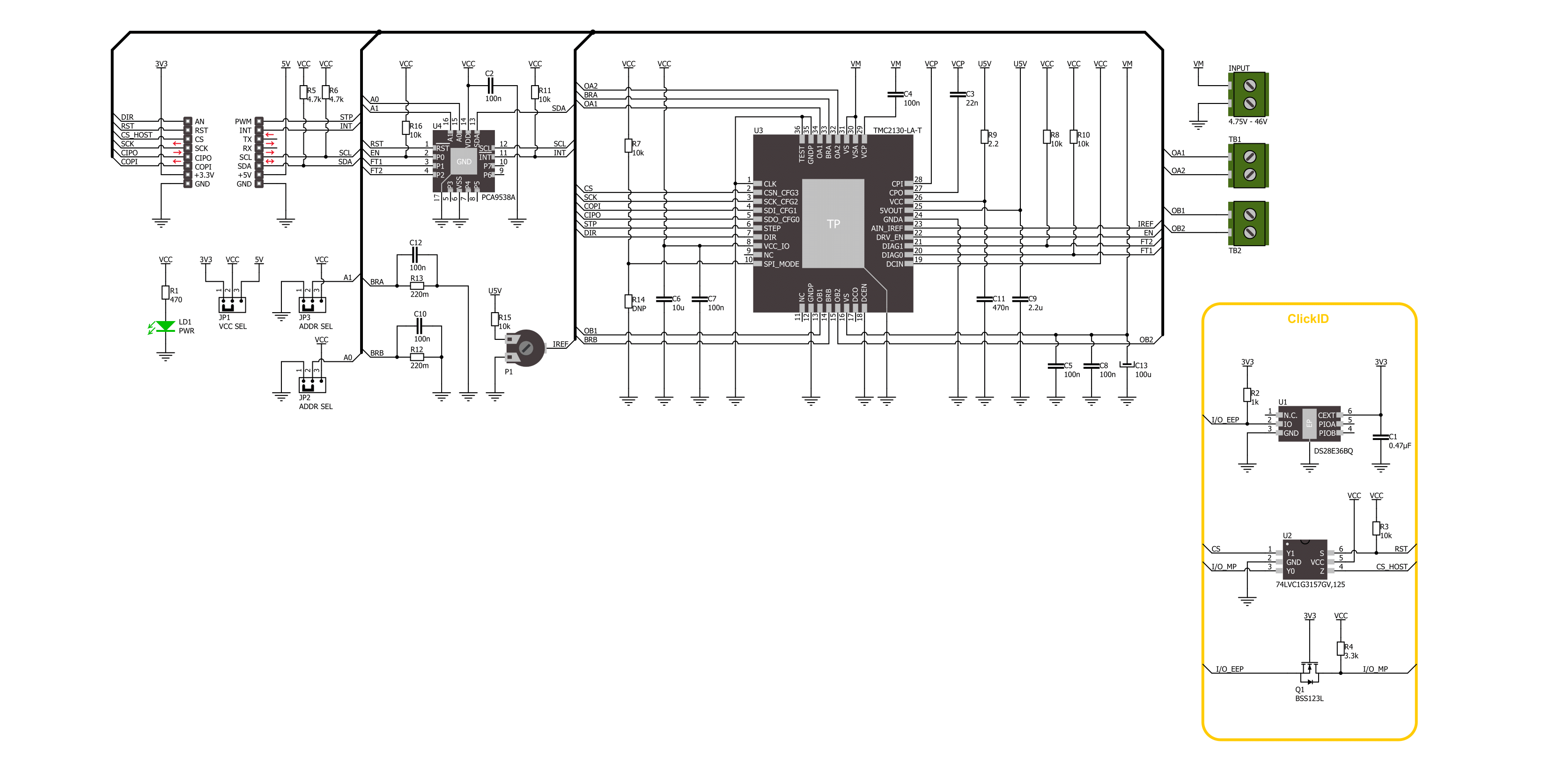
Silent Step 2 Click is based on the TMC2130, a high-performance two-phase stepper motor driver from Analog Devices. The highest resolution is 256 microsteps per full step. Some other integrated techniques are SpreadCycle™ as a highly dynamic motor control chopper, DcStep™ as load-dependent speed control, sTallGuard2™ as a high precision sensorless motor load detection, and more. The motor driver supports passive breaking and freewheeling mode. This motor driver also supports a few operating modes that can be used per your needs. Silent Step 2 Click can communicate with the host MCU using a standard 4-wire SPI serial interface. It can also use the
step/direction driver mode, which allows you to control the motor position by sending pulses on the step signal STP pin while indicating the direction on the direction signal DIR pin. The driver uses an external motor power supply of 4.75 up to 43V to power a 2-phase stepper motor up to 2A coil current (2.5A peak). The motor current can be set over the onboard VREF potentiometer. Additional functionalities on this Click board™ are achieved over the PCA9538A, an 8-bit I/O port from NXP. This I/O port communicates with the host MCU over the I2C interface, and you can change the I2C address over the ADDR SEL jumpers. The PCA9538A allows you to control the driver enable
function of the motor driver. It also monitors two driver motors' diagnostic outputs, and if a condition is met (say, stall of the motor), it will interrupt the host MCU over the INT pin. The I/O port can be reset over the RST pin. This Click board™ can operate with either 3.3V or 5V logic voltage levels selected via the VCC SEL jumper. This way, both 3.3V and 5V capable MCUs can use the communication lines properly. Also, this Click board™ comes equipped with a library containing easy-to-use functions and an example code that can be used as a reference for further development.

Features overview
Development board
Arduino UNO is a versatile microcontroller board built around the ATmega328P chip. It offers extensive connectivity options for various projects, featuring 14 digital input/output pins, six of which are PWM-capable, along with six analog inputs. Its core components include a 16MHz ceramic resonator, a USB connection, a power jack, an
ICSP header, and a reset button, providing everything necessary to power and program the board. The Uno is ready to go, whether connected to a computer via USB or powered by an AC-to-DC adapter or battery. As the first USB Arduino board, it serves as the benchmark for the Arduino platform, with "Uno" symbolizing its status as the
first in a series. This name choice, meaning "one" in Italian, commemorates the launch of Arduino Software (IDE) 1.0. Initially introduced alongside version 1.0 of the Arduino Software (IDE), the Uno has since become the foundational model for subsequent Arduino releases, embodying the platform's evolution.

Microcontroller Overview
MCU Card / MCU

Architecture
AVR
MCU Memory (KB)
32
Silicon Vendor
Microchip
Pin count
28
RAM (Bytes)
2048
You complete me!
Accessories
Click Shield for Arduino UNO has two proprietary mikroBUS™ sockets, allowing all the Click board™ devices to be interfaced with the Arduino UNO board without effort. The Arduino Uno, a microcontroller board based on the ATmega328P, provides an affordable and flexible way for users to try out new concepts and build prototypes with the ATmega328P microcontroller from various combinations of performance, power consumption, and features. The Arduino Uno has 14 digital input/output pins (of which six can be used as PWM outputs), six analog inputs, a 16 MHz ceramic resonator (CSTCE16M0V53-R0), a USB connection, a power jack, an ICSP header, and reset button. Most of the ATmega328P microcontroller pins are brought to the IO pins on the left and right edge of the board, which are then connected to two existing mikroBUS™ sockets. This Click Shield also has several switches that perform functions such as selecting the logic levels of analog signals on mikroBUS™ sockets and selecting logic voltage levels of the mikroBUS™ sockets themselves. Besides, the user is offered the possibility of using any Click board™ with the help of existing bidirectional level-shifting voltage translators, regardless of whether the Click board™ operates at a 3.3V or 5V logic voltage level. Once you connect the Arduino UNO board with our Click Shield for Arduino UNO, you can access hundreds of Click boards™, working with 3.3V or 5V logic voltage levels.

The 28BYJ-48 is an adaptable 5VDC stepper motor with a compact design, ideal for various applications. It features four phases, a speed variation ratio of 1/64, and a stride angle of 5.625°/64 steps, allowing precise control. The motor operates at a frequency of 100Hz and has a DC resistance of 50Ω ±7% at 25°C. It boasts an idle in-traction frequency greater than 600Hz and an idle out-traction frequency exceeding 1000Hz, ensuring reliability in different scenarios. With a self-positioning torque and in-traction torque both exceeding 34.3mN.m at 120Hz, the 28BYJ-48 offers robust performance. Its friction torque ranges from 600 to 1200 gf.cm, while the pull-in torque is 300 gf.cm. This motor makes a reliable and efficient choice for your stepper motor needs.

Used MCU Pins
mikroBUS™ mapper
Take a closer look
Click board™ Schematic
Step by step
Project assembly

Start by selecting your development board and Click board™. Begin with the Arduino UNO Rev3 as your development board.


Track your results in real time
Application Output
1. Application Output - In Debug mode, the 'Application Output' window enables real-time data monitoring, offering direct insight into execution results. Ensure proper data display by configuring the environment correctly using the provided tutorial.

2. UART Terminal - Use the UART Terminal to monitor data transmission via a USB to UART converter, allowing direct communication between the Click board™ and your development system. Configure the baud rate and other serial settings according to your project's requirements to ensure proper functionality. For step-by-step setup instructions, refer to the provided tutorial.

3. Plot Output - The Plot feature offers a powerful way to visualize real-time sensor data, enabling trend analysis, debugging, and comparison of multiple data points. To set it up correctly, follow the provided tutorial, which includes a step-by-step example of using the Plot feature to display Click board™ readings. To use the Plot feature in your code, use the function: plot(*insert_graph_name*, variable_name);. This is a general format, and it is up to the user to replace 'insert_graph_name' with the actual graph name and 'variable_name' with the parameter to be displayed.

Software Support
Library Description
This library contains API for Silent Step 2 Click driver.
Key functions:
silentstep2_rotate_by_angle- Silent Step 2 rotates the shaft through a desired angle function.silentstep2_set_direction- Silent Step 2 sets the clockwise or counterclockwise direction movement function.
Open Source
Code example
The complete application code and a ready-to-use project are available through the NECTO Studio Package Manager for direct installation in the NECTO Studio. The application code can also be found on the MIKROE GitHub account.
/*!
 * @file main.c
 * @brief Silent Step 2 Click example
 *
 * # Description
 * This example demonstrates the use of Silent Step 2 Click board™
 * by driving the motor in both directions for a desired rotation angle.
 *
 * The demo application is composed of two sections :
 *
 * ## Application Init
 * The initialization of I2C and SPI module and log UART.
 * After driver initialization, the app sets the default configuration.
 *
 * ## Application Task
 * The application task represents an example that demonstrates
 * the use of the Silent Step 2 Click board™ with which the user can sequentially move the motor.
 * The first part of the sequence executes the clockwise/counterclockwise motor movement
 * for an angle of 90 degrees with a step speed of 50%,
 * all the way to the last sequence of the same movement routine
 * of 360 degree angle with a step speed of 90%.
 * Results are being sent to the UART Terminal, where you can track their changes.
 *
 * @author Nenad Filipovic
 *
 */

#include "board.h"
#include "log.h"
#include "silentstep2.h"

static silentstep2_t silentstep2;
static log_t logger;

// Bipolar stepper motor, resolution of 200 steps per revolution (1.8 degrees)
#define SILENTSTEP2_STEP_RES_200    200

void application_init ( void )
{
    log_cfg_t log_cfg;  /**< Logger config object. */
    silentstep2_cfg_t silentstep2_cfg;  /**< Click config object. */

    /**
     * Logger initialization.
     * Default baud rate: 115200
     * Default log level: LOG_LEVEL_DEBUG
     * @note If USB_UART_RX and USB_UART_TX
     * are defined as HAL_PIN_NC, you will
     * need to define them manually for log to work.
     * See @b LOG_MAP_USB_UART macro definition for detailed explanation.
     */
    LOG_MAP_USB_UART( log_cfg );
    log_init( &logger, &log_cfg );
    log_info( &logger, " Application Init " );

    // Click initialization.
    silentstep2_cfg_setup( &silentstep2_cfg );
    SILENTSTEP2_MAP_MIKROBUS( silentstep2_cfg, MIKROBUS_1 );
    err_t init_flag = silentstep2_init( &silentstep2, &silentstep2_cfg );
    if ( ( I2C_MASTER_ERROR == init_flag ) || ( SPI_MASTER_ERROR == init_flag ) )
    {
        log_error( &logger, " Communication init." );
        for ( ; ; );
    }

    if ( SILENTSTEP2_ERROR == silentstep2_default_cfg ( &silentstep2 ) )
    {
        log_error( &logger, " Default configuration." );
        for ( ; ; );
    }

    log_info( &logger, " Application Task " );
    log_printf( &logger, "-----------------------------\r\n" );
    Delay_ms ( 100 );
}

void application_task ( void )
{
    log_printf( &logger, " Clockwise motion\r\n" );
    log_printf( &logger, " Angle of rotation :  90 degrees\r\n" );
    log_printf( &logger, " Step speed        :  50 %%\r\n" );
    silentstep2_set_direction( &silentstep2, SILENTSTEP2_DIRECTION_CLOCKWISE );
    if ( SILENTSTEP2_OK == silentstep2_rotate_by_angle( &silentstep2, 50, 90, SILENTSTEP2_STEP_RES_200 ) )
    {
        log_printf( &logger, "-----------------------------\r\n" );
        Delay_ms ( 1000 );
        Delay_ms ( 1000 );
    }

    log_printf( &logger, " Counterclockwise motion\r\n" );
    log_printf( &logger, " Angle of rotation :  180 deg\r\n" );
    log_printf( &logger, " Step speed        :  50 %%\r\n" );
    silentstep2_set_direction( &silentstep2, SILENTSTEP2_DIRECTION_COUNTERCLOCKWISE );
    if ( SILENTSTEP2_OK == silentstep2_rotate_by_angle( &silentstep2, 50, 180, SILENTSTEP2_STEP_RES_200 ) )
    {
        log_printf( &logger, "-----------------------------\r\n" );
        Delay_ms ( 1000 );
        Delay_ms ( 1000 );
    }

    log_printf( &logger, " Clockwise motion\r\n" );
    log_printf( &logger, " Angle of rotation : 270 deg\r\n" );
    log_printf( &logger, " Step speed        :  50 %% \r\n" );
    silentstep2_set_direction( &silentstep2, SILENTSTEP2_DIRECTION_CLOCKWISE );
    if ( SILENTSTEP2_OK == silentstep2_rotate_by_angle( &silentstep2, 50, 270, SILENTSTEP2_STEP_RES_200 ) )
    {
        log_printf( &logger, "-----------------------------\r\n" );
        Delay_ms ( 1000 );
        Delay_ms ( 1000 );
    }

    log_printf( &logger, " Counterclockwise motion\r\n" );
    log_printf( &logger, " Angle of rotation : 360 deg\r\n" );
    log_printf( &logger, " Step speed        : 90 %%\r\n" );
    silentstep2_set_direction( &silentstep2, SILENTSTEP2_DIRECTION_COUNTERCLOCKWISE );
    if ( SILENTSTEP2_OK == silentstep2_rotate_by_angle( &silentstep2, 90, 360, SILENTSTEP2_STEP_RES_200 ) )
    {
        log_printf( &logger, "-----------------------------\r\n" );
        Delay_ms ( 1000 );
        Delay_ms ( 1000 );
    }

    log_printf( &logger, " Clockwise motion\r\n" );
    log_printf( &logger, " Angle of rotation : 360 deg\r\n" );
    log_printf( &logger, " Step speed        : 90 %% \r\n" );
    silentstep2_set_direction( &silentstep2, SILENTSTEP2_DIRECTION_CLOCKWISE );
    if ( SILENTSTEP2_OK == silentstep2_rotate_by_angle( &silentstep2, 90, 360, SILENTSTEP2_STEP_RES_200 ) )
    {
        log_printf( &logger, "-----------------------------\r\n" );
        Delay_ms ( 1000 );
        Delay_ms ( 1000 );
    }
}

int main ( void )
{
    /* Do not remove this line or clock might not be set correctly. */
    #ifdef PREINIT_SUPPORTED
    preinit();
    #endif

    application_init( );

    for ( ; ; )
    {
        application_task( );
    }

    return 0;
}

// ------------------------------------------------------------------------ END
Additional Support
Resources
Category:Stepper


