Experience groundbreaking UWB technology with DWM1000 and ATmega328
Where every centimeter counts

Published Feb 14, 2024
Click board™
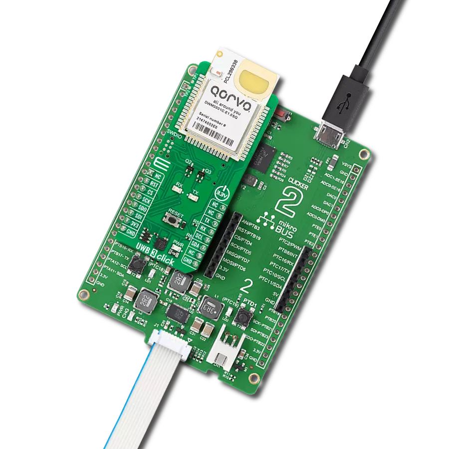
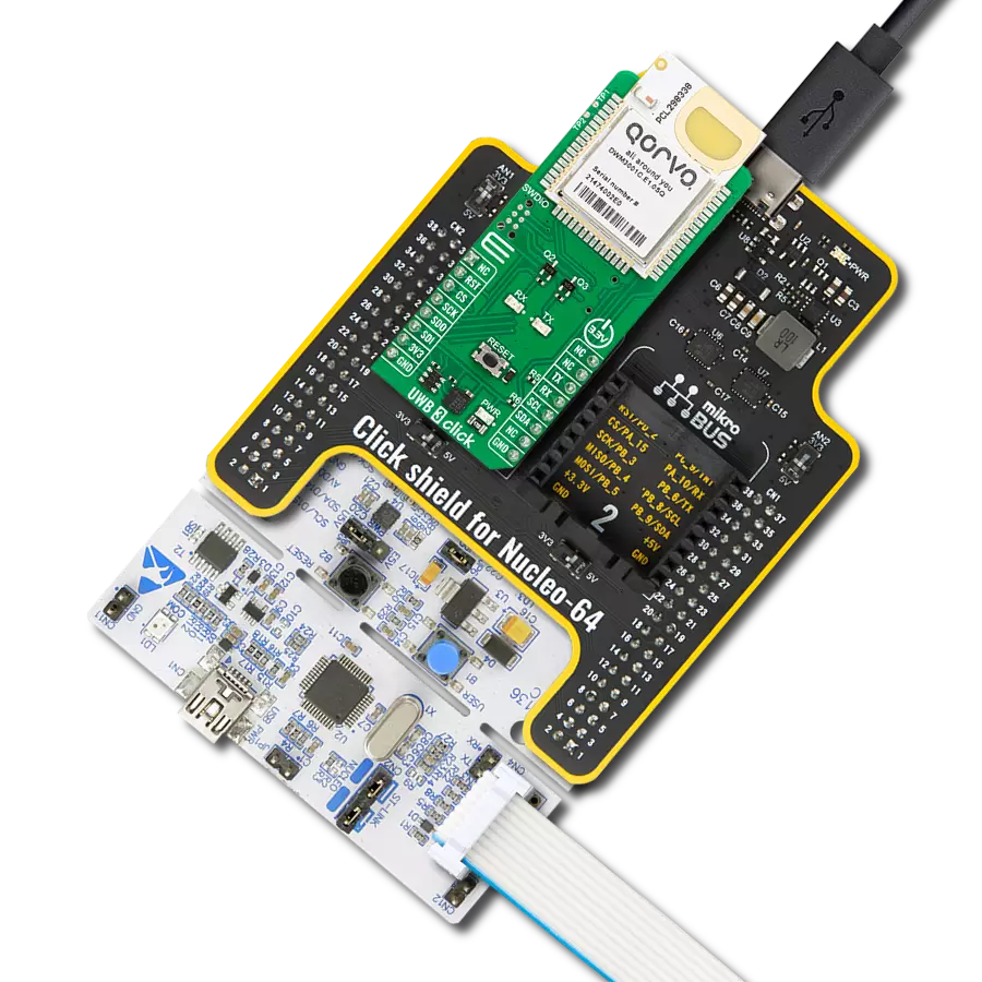
UWB Click
Dev. board
Arduino UNO Rev3
Compiler
NECTO Studio
MCU
ATmega328
Our UWB transceiver sets a new standard in 2-way ranging and TDOA systems, ensuring 10cm accuracy for applications such as indoor positioning, asset management, and beyond.
A
A
Hardware Overview
How does it work?
UWB Click is based on the DWM1000, UWB-compliant wireless transceiver module from Qorvo. RF components, Qorvo UWB transceiver, and other components reside on-module. DWM1000 enables cost-effective and reduced complexity integration of UWB communications and ranging features, greatly accelerating design implementation. This module enables the location of objects in real-time location systems (RTLS) to a precision of 10cm indoors, high data rate communications up to 6.8 Mbps, and excellent communications range of up to 300m thanks to coherent receiver techniques. The module contains an on-board 38.4 MHz reference crystal, which has been trimmed in production to reduce the initial frequency error to approximately 2 ppm, using the transceiver’s internal on-chip crystal trimming circuit. The DWM1000 module communicates with MCU using the standard SPI serial interface with a maximum SPI frequency of 20 MHz. This module also has several GPIO pins, while in this case
two of them are used to drive LED indicators that notify the user which configuration of the transceiver is used (TX or RX). Also, it possesses Reset and Interrupt pins routed to the INT and RST pin of the mikroBUS™. When power is applied to the DWM1000, the RST pin is driven low by internal circuitry as part of its power-up sequence. RST remains low until the on-module crystal oscillator has powered up and its output is suitable for use by the rest of the device, at which time RST is stated high. RST pin may also be used as an output to reset external circuitry as part of system bring-up as power is applied. Always-On (AON) memory can be used to retain DWM1000 configuration data during the lowest power operational states when the on-chip voltage regulators are disabled. Depending on the end-use applications and the system design, DWM1000 settings may need to be tuned. To help with this tuning several built-in functions such as continuous wave TX and continuous packet transmission can be enabled. To maximize range,
DWM1000 transmit power spectral density (PSD) should be set to the maximum allowable for the geographic region in which it will be used. As the module contains an integrated antenna, the transmit power can only be measured over the air. The DWM1000 provides the facility to adjust the transmit power, and these adjustments can be used to maximize transmit power whilst meeting the regulatory spectral mask. This Click board™ uses the SPI communication interface. It is designed to be operated only with 3.3V logic levels. A proper logic voltage level conversion should be performed before the Click board™ is used with MCUs with logic levels of 5V. More information about the DWM1000’s functionality, electrical specifications, and typical performance can be found in the attached datasheet. However, the Click board™ comes equipped with a library that contains easy to use functions and a usage example that may be used as a reference for the development.

Features overview
Development board
Arduino UNO is a versatile microcontroller board built around the ATmega328P chip. It offers extensive connectivity options for various projects, featuring 14 digital input/output pins, six of which are PWM-capable, along with six analog inputs. Its core components include a 16MHz ceramic resonator, a USB connection, a power jack, an
ICSP header, and a reset button, providing everything necessary to power and program the board. The Uno is ready to go, whether connected to a computer via USB or powered by an AC-to-DC adapter or battery. As the first USB Arduino board, it serves as the benchmark for the Arduino platform, with "Uno" symbolizing its status as the
first in a series. This name choice, meaning "one" in Italian, commemorates the launch of Arduino Software (IDE) 1.0. Initially introduced alongside version 1.0 of the Arduino Software (IDE), the Uno has since become the foundational model for subsequent Arduino releases, embodying the platform's evolution.

Microcontroller Overview
MCU Card / MCU

Architecture
AVR
MCU Memory (KB)
32
Silicon Vendor
Microchip
Pin count
32
RAM (Bytes)
2048
You complete me!
Accessories
Click Shield for Arduino UNO has two proprietary mikroBUS™ sockets, allowing all the Click board™ devices to be interfaced with the Arduino UNO board without effort. The Arduino Uno, a microcontroller board based on the ATmega328P, provides an affordable and flexible way for users to try out new concepts and build prototypes with the ATmega328P microcontroller from various combinations of performance, power consumption, and features. The Arduino Uno has 14 digital input/output pins (of which six can be used as PWM outputs), six analog inputs, a 16 MHz ceramic resonator (CSTCE16M0V53-R0), a USB connection, a power jack, an ICSP header, and reset button. Most of the ATmega328P microcontroller pins are brought to the IO pins on the left and right edge of the board, which are then connected to two existing mikroBUS™ sockets. This Click Shield also has several switches that perform functions such as selecting the logic levels of analog signals on mikroBUS™ sockets and selecting logic voltage levels of the mikroBUS™ sockets themselves. Besides, the user is offered the possibility of using any Click board™ with the help of existing bidirectional level-shifting voltage translators, regardless of whether the Click board™ operates at a 3.3V or 5V logic voltage level. Once you connect the Arduino UNO board with our Click Shield for Arduino UNO, you can access hundreds of Click boards™, working with 3.3V or 5V logic voltage levels.

Used MCU Pins
mikroBUS™ mapper
Take a closer look
Click board™ Schematic

Step by step
Project assembly

Start by selecting your development board and Click board™. Begin with the Arduino UNO Rev3 as your development board.


Software Support
Library Description
This library contains API for UWB Click driver.
Key functions:
uwb_set_mode- This function set device working mode.uwb_get_transmit_status- This function get transmit status.uwb_start_transceiver- This function start communication of device.
Open Source
Code example
The complete application code and a ready-to-use project are available through the NECTO Studio Package Manager for direct installation in the NECTO Studio. The application code can also be found on the MIKROE GitHub account.
/*!
 * \file
 * \brief Uwb Click example
 *
 * # Description
 * UWB Click sends and receive data, depending on the selected device mode.
 *
 * The demo application is composed of two sections :
 *
 * ## Application Init
 * Initializes the driver and configures the Click board for the selected mode.
 *
 * ## Application Task
 * Depending on the selected mode, it reads all the received data or sends the desired message
 * every 2 seconds.
 *
 * \author MikroE Team
 *
 */
// ------------------------------------------------------------------- INCLUDES

#include "board.h"
#include "log.h"
#include "uwb.h"

// ------------------------------------------------------------------ VARIABLES

static uwb_t uwb;
static log_t logger;

// Device mode setter - selects the module working mode RX(receiver)/TX(transmitter)
static uint8_t dev_mode = UWB_MODE_TX;

// Transmit buffers
static uint8_t data_tx_1[ 7 ] = "MikroE";
static uint8_t data_tx_2[ 10 ] = "UWB Click";

// Transmit length read var
static uint16_t temp_len = 0;

// Recieved data buffer
static uint8_t transmit_data[ 256 ] = { 0 };

// Dev_status var
static uint8_t dev_status = { 0 };

// ------------------------------------------------------ APPLICATION FUNCTIONS

void application_init ( void )
{
    log_cfg_t log_cfg;
    uwb_cfg_t cfg;

    /**
     * Logger initialization.
     * Default baud rate: 115200
     * Default log level: LOG_LEVEL_DEBUG
     * @note If USB_UART_RX and USB_UART_TX
     * are defined as HAL_PIN_NC, you will
     * need to define them manually for log to work.
     * See @b LOG_MAP_USB_UART macro definition for detailed explanation.
     */
    LOG_MAP_USB_UART( log_cfg );
    log_init( &logger, &log_cfg );
    log_info( &logger, "---- Application Init ----" );

    // Click initialization.
    uwb_cfg_setup( &cfg );
    UWB_MAP_MIKROBUS( cfg, MIKROBUS_1 );
    uwb_init( &uwb, &cfg );
    Delay_ms ( 100 );

    uwb_enable ( &uwb );
    Delay_ms ( 100 );

    uint8_t id_raw[ 4 ] = { 0 };
    uwb.offset = UWB_SUB_NO;
    uwb_generic_read( &uwb, UWB_REG_DEV_ID, &id_raw[ 0 ], 4 );

    uint16_t tag_data = ( ( uint16_t ) id_raw[ 3 ] << 8 ) | id_raw[ 2 ];

    if ( UWB_TAG != tag_data )
    {
        log_printf( &logger, " ***** ERROR ***** \r\n" );
        for ( ; ; );
    }

    uwb_set_mode( &uwb, UWB_MODE_IDLE );

    //-----------------------------------------------------

    // Setting device mode and interrupt for that mode as well as clearing dev_status reg.
    uwb_set_mode( &uwb, dev_mode );
    uwb_int_mask_set( &uwb );
    uwb_clear_status( &uwb );

    // Setting device address and network ID
    log_printf( &logger, " ******************** \r\n" );
    if ( UWB_MODE_RX == dev_mode )
    {
        uwb_set_dev_adr_n_network_id( &uwb, 6, 10 );
        log_printf( &logger, " ***** RECEIVER ***** \r\n" );
    }
    else if ( UWB_MODE_TX == dev_mode )
    {
        uwb_set_dev_adr_n_network_id( &uwb, 5, 10 );
        log_printf( &logger, " **** TRANSMITER **** \r\n" );
    }
    log_printf( &logger, " ******************** \r\n" );

    Delay_ms ( 100 );

    // Setting default configuartion and tuning device for that configuration
    uwb_use_smart_power( &uwb, UWB_LOW );
    uwb_frame_check( UWB_LOW );
    uwb_frame_filter( &uwb, UWB_LOW );
    uwb_set_transmit_type( &uwb, &UWB_TMODE_LONGDATA_RANGE_LOWPOWER[ 0 ] );
    uwb_set_channel( &uwb, UWB_CHANNEL_5 );
    uwb_tune_config( &uwb );

    Delay_ms ( 100 );

    if ( UWB_MODE_RX == dev_mode )
    {
        // Setup for first receive
        uwb_set_mode( &uwb, UWB_MODE_IDLE );
        uwb_set_bit ( &uwb, UWB_REG_SYS_CFG, 29, UWB_HIGH );
        uwb_set_bit ( &uwb, UWB_REG_SYS_CFG, 30, UWB_HIGH );
        uwb_set_bit ( &uwb, UWB_REG_SYS_CFG, 31, UWB_HIGH );
        uwb_set_mode( &uwb, UWB_MODE_RX );
        uwb_clear_status( &uwb );
        uwb_start_transceiver( &uwb );
    }
    else if ( UWB_MODE_TX == dev_mode )
    {
        // Setup for first transmit
        uwb_set_mode( &uwb, UWB_MODE_IDLE );
        uwb_clear_status( &uwb );
        uwb_set_transmit( &uwb, &data_tx_1[ 0 ], 6 );
        uwb_set_mode( &uwb, UWB_MODE_TX );
        uwb_start_transceiver( &uwb );
        log_printf( &logger, " - Transmit 1 done - \r\n" );
    }

    log_printf( &logger, " ***** APP TASK ***** \r\n" );
    Delay_ms ( 1000 );
    Delay_ms ( 1000 );
}

void application_task ( void )
{
    dev_status = uwb_get_qint_pin_status( &uwb );

    if ( UWB_MODE_RX == dev_mode )
    {
        if ( dev_status )
        {
            // Reading transmitted data, logs it and resetting to receive mode
            uwb_set_mode( &uwb, UWB_MODE_IDLE );
            uwb_clear_status( &uwb );
            temp_len = uwb_get_transmit_len( &uwb );
            uwb_get_transmit( &uwb, &transmit_data[ 0 ], temp_len );
            log_printf( &logger, "Received data: %s\r\n", transmit_data );
            log_printf( &logger, " - Receive done - \r\n" );
            uwb_set_mode( &uwb, UWB_MODE_RX );
            uwb_start_transceiver( &uwb );
        }
    }
    else if ( UWB_MODE_TX == dev_mode )
    {
        if ( dev_status )
        {
            // Transmits data, resetting to transmit mode and sets 2sec delay
            uwb_set_mode( &uwb, UWB_MODE_IDLE );
            uwb_clear_status( &uwb );
            uwb_set_transmit( &uwb, &data_tx_2[ 0 ], 9 );
            uwb_set_mode( &uwb, UWB_MODE_TX );
            uwb_start_transceiver( &uwb );
            log_printf( &logger, " - Transmit 2 done - \r\n" );
            Delay_ms ( 1000 );
            Delay_ms ( 1000 );
            uwb_set_mode( &uwb, UWB_MODE_IDLE );
            uwb_clear_status( &uwb );
            uwb_set_transmit( &uwb, &data_tx_1[ 0 ], 6 );
            uwb_set_mode( &uwb, UWB_MODE_TX );
            uwb_start_transceiver( &uwb );
            log_printf( &logger, " - Transmit 1 done - \r\n" );
            Delay_ms ( 1000 );
            Delay_ms ( 1000 );
        }
    }
}

int main ( void )
{
    /* Do not remove this line or clock might not be set correctly. */
    #ifdef PREINIT_SUPPORTED
    preinit();
    #endif

    application_init( );

    for ( ; ; )
    {
        application_task( );
    }

    return 0;
}


// ------------------------------------------------------------------------ END
Additional Support
Resources
Category:UWB