Improve reliability through continuous VCP analysis using INA239 and ATmega328P
Your circuit's guardian: VCP monitoring for peak performance

Published Feb 14, 2024
Click board™
VCP Monitor 4 Click
Dev. board
Arduino UNO Rev3
Compiler
NECTO Studio
MCU
ATmega328P
Our VCP monitoring solution is designed to provide you with precise and real-time measurements of voltage, current, and power parameters, ensuring the optimal operation of your electronic circuits
A
A
Hardware Overview
How does it work?
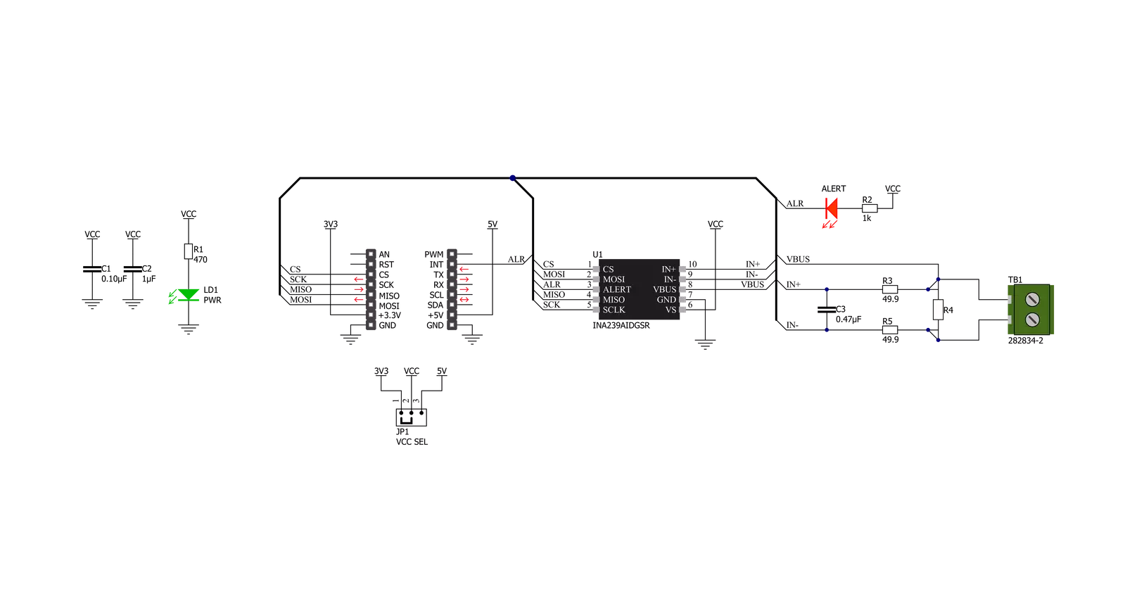
VCP Monitor 4 Click is based on the INA239, a digital current sense amplifier with a 4-wire serial digital interface from Texas Instruments. It measures shunt and bus voltage and internal temperature while calculating the power necessary for accurate decision-making in precisely controlled systems. The input stage of the INA239 is designed such that the input common-mode voltage can be higher than the device supply voltage. It operates from mikroBUS™ power rails but can measure voltage and current as high as 85V, making it well-suited
for high- and low-side current measurements. Its integrated 16-bit ADC allows for selectable conversion times from 50μs to 4.12ms and sample averaging from 1x to 1024x, which further helps reduce the noise of the measured data. It also features low offset and gain-drift and low input bias current, which reduces the current consumed in both Active and Shutdown operational states. Another benefit of low bias current is that it allows the use of larger current-sense resistors (in this case, onboard R4 shunt 25MΩ resistor), thus providing accurate current measurements in
the micro-amp range. Besides it can also measure the temperature through the integrated temperature sensor. This Click board™ can operate with either 3.3V or 5V logic voltage levels selected via the VCC SEL jumper. This way, both 3.3V and 5V capable MCUs can use the communication lines properly. Also, this Click board™ comes equipped with a library containing easy-to-use functions and an example code that can be used as a reference for further development.

Features overview
Development board
Arduino UNO is a versatile microcontroller board built around the ATmega328P chip. It offers extensive connectivity options for various projects, featuring 14 digital input/output pins, six of which are PWM-capable, along with six analog inputs. Its core components include a 16MHz ceramic resonator, a USB connection, a power jack, an
ICSP header, and a reset button, providing everything necessary to power and program the board. The Uno is ready to go, whether connected to a computer via USB or powered by an AC-to-DC adapter or battery. As the first USB Arduino board, it serves as the benchmark for the Arduino platform, with "Uno" symbolizing its status as the
first in a series. This name choice, meaning "one" in Italian, commemorates the launch of Arduino Software (IDE) 1.0. Initially introduced alongside version 1.0 of the Arduino Software (IDE), the Uno has since become the foundational model for subsequent Arduino releases, embodying the platform's evolution.

Microcontroller Overview
MCU Card / MCU

Architecture
AVR
MCU Memory (KB)
32
Silicon Vendor
Microchip
Pin count
28
RAM (Bytes)
2048
You complete me!
Accessories
Click Shield for Arduino UNO has two proprietary mikroBUS™ sockets, allowing all the Click board™ devices to be interfaced with the Arduino UNO board without effort. The Arduino Uno, a microcontroller board based on the ATmega328P, provides an affordable and flexible way for users to try out new concepts and build prototypes with the ATmega328P microcontroller from various combinations of performance, power consumption, and features. The Arduino Uno has 14 digital input/output pins (of which six can be used as PWM outputs), six analog inputs, a 16 MHz ceramic resonator (CSTCE16M0V53-R0), a USB connection, a power jack, an ICSP header, and reset button. Most of the ATmega328P microcontroller pins are brought to the IO pins on the left and right edge of the board, which are then connected to two existing mikroBUS™ sockets. This Click Shield also has several switches that perform functions such as selecting the logic levels of analog signals on mikroBUS™ sockets and selecting logic voltage levels of the mikroBUS™ sockets themselves. Besides, the user is offered the possibility of using any Click board™ with the help of existing bidirectional level-shifting voltage translators, regardless of whether the Click board™ operates at a 3.3V or 5V logic voltage level. Once you connect the Arduino UNO board with our Click Shield for Arduino UNO, you can access hundreds of Click boards™, working with 3.3V or 5V logic voltage levels.

Used MCU Pins
mikroBUS™ mapper
Take a closer look
Click board™ Schematic
Step by step
Project assembly

Start by selecting your development board and Click board™. Begin with the Arduino UNO Rev3 as your development board.


Track your results in real time
Application Output
1. Application Output - In Debug mode, the 'Application Output' window enables real-time data monitoring, offering direct insight into execution results. Ensure proper data display by configuring the environment correctly using the provided tutorial.

2. UART Terminal - Use the UART Terminal to monitor data transmission via a USB to UART converter, allowing direct communication between the Click board™ and your development system. Configure the baud rate and other serial settings according to your project's requirements to ensure proper functionality. For step-by-step setup instructions, refer to the provided tutorial.

3. Plot Output - The Plot feature offers a powerful way to visualize real-time sensor data, enabling trend analysis, debugging, and comparison of multiple data points. To set it up correctly, follow the provided tutorial, which includes a step-by-step example of using the Plot feature to display Click board™ readings. To use the Plot feature in your code, use the function: plot(*insert_graph_name*, variable_name);. This is a general format, and it is up to the user to replace 'insert_graph_name' with the actual graph name and 'variable_name' with the parameter to be displayed.

Software Support
Library Description
This library contains API for VCP Monitor 4 Click driver.
Key functions:
vcpmonitor4_get_vbus- Get BUS voltagevcpmonitor4_get_current- Get Currentvcpmonitor4_get_power- Get Shunt voltage.
Open Source
Code example
The complete application code and a ready-to-use project are available through the NECTO Studio Package Manager for direct installation in the NECTO Studio. The application code can also be found on the MIKROE GitHub account.
/*!
 * @file main.c
 * @brief VCPMonitor4 Click example
 *
 * # Description
 * This example application showcases ability of Click board
 * to be configured for different readings and read temperature,
 * voltage, current and power.
 *
 * The demo application is composed of two sections :
 *
 * ## Application Init
 * Initialization of communication modules (SPI, UART) and
 * additional alert pin. Reads Manufacturer and Device ID,
 * Configurates device for reading all device measurements.
 *
 * ## Application Task
 * In span of 500ms reads and calculates data for IC temperature,
 * Bus voltage in V, Shunt voltage in mV, and current and power for device.
 *
 * @author Luka Filipovic
 *
 */

#include "board.h"
#include "log.h"
#include "vcpmonitor4.h"

static vcpmonitor4_t vcpmonitor4;
static log_t logger;

float current_lsb;

void application_init ( void )
{
    log_cfg_t log_cfg;  /**< Logger config object. */
    vcpmonitor4_cfg_t vcpmonitor4_cfg;  /**< Click config object. */

    /**
     * Logger initialization.
     * Default baud rate: 115200
     * Default log level: LOG_LEVEL_DEBUG
     * @note If USB_UART_RX and USB_UART_TX
     * are defined as HAL_PIN_NC, you will
     * need to define them manually for log to work.
     * See @b LOG_MAP_USB_UART macro definition for detailed explanation.
     */
    LOG_MAP_USB_UART( log_cfg );
    log_init( &logger, &log_cfg );
    log_info( &logger, " Application Init " );

    // Click initialization.
    vcpmonitor4_cfg_setup( &vcpmonitor4_cfg );
    VCPMONITOR4_MAP_MIKROBUS( vcpmonitor4_cfg, MIKROBUS_1 );
    err_t init_flag  = vcpmonitor4_init( &vcpmonitor4, &vcpmonitor4_cfg );
    VCPMONITOR4_SET_DATA_SAMPLE_EDGE
    if ( SPI_MASTER_ERROR == init_flag )
    {
        log_error( &logger, " Application Init Error. " );
        log_info( &logger, " Please, run program again... " );

        for ( ; ; );
    }

    uint32_t temp_data = 0;
    vcpmonitor4_generic_read( &vcpmonitor4, VCPMONITOR4_REG_MANUFACTURER_ID, &temp_data );
    log_printf( &logger, " > Manufacturer ID: \t0x%.4X\r\n", temp_data );

    vcpmonitor4_generic_read( &vcpmonitor4, VCPMONITOR4_REG_DEVICE_ID, &temp_data );
    log_printf( &logger, " > Device ID: \t\t0x%.4X\r\n", temp_data );

    vcpmonitor4_default_cfg ( &vcpmonitor4 );
    Delay_ms ( 1000 );
    log_info( &logger, " Application Task " );
}

void application_task ( void )
{
    float read_data;
    vcpmonitor4_get_temperature( &vcpmonitor4, &read_data );
    log_printf( &logger, " > Temperature:\t%.2f \r\n", read_data );

    vcpmonitor4_get_vbus( &vcpmonitor4, &read_data );
    log_printf( &logger, " > Vbus[V]:\t%.2f \r\n", read_data );

    vcpmonitor4_get_vshunt( &vcpmonitor4, &read_data );
    log_printf( &logger, " > Vshunt[mV]:\t%.2f \r\n", read_data );

    vcpmonitor4_get_current( &vcpmonitor4, &read_data );
    log_printf( &logger, " > Current[A]:\t%.2f \r\n", read_data );

    vcpmonitor4_get_power( &vcpmonitor4, &read_data );
    log_printf( &logger, " > Power[W]:\t%.2f \r\n", read_data );
    log_printf( &logger, "*************************\r\n" );

    Delay_ms ( 500 );
}

int main ( void )
{
    /* Do not remove this line or clock might not be set correctly. */
    #ifdef PREINIT_SUPPORTED
    preinit();
    #endif

    application_init( );

    for ( ; ; )
    {
        application_task( );
    }

    return 0;
}

// ------------------------------------------------------------------------ END
Additional Support
Resources
Category:Measurements


