Enable users to tailor vibration patterns to their preferences using G0832022D and ATmega328P
Shake up your world with control

Published Feb 14, 2024
Click board™
Vibro Motor 3 Click
Dev. board
Arduino UNO Rev3
Compiler
NECTO Studio
MCU
ATmega328P
Fine-tune your device notifications with precision, ensuring that users receive alerts in a more discreet and personalized manner
A
A
Hardware Overview
How does it work?
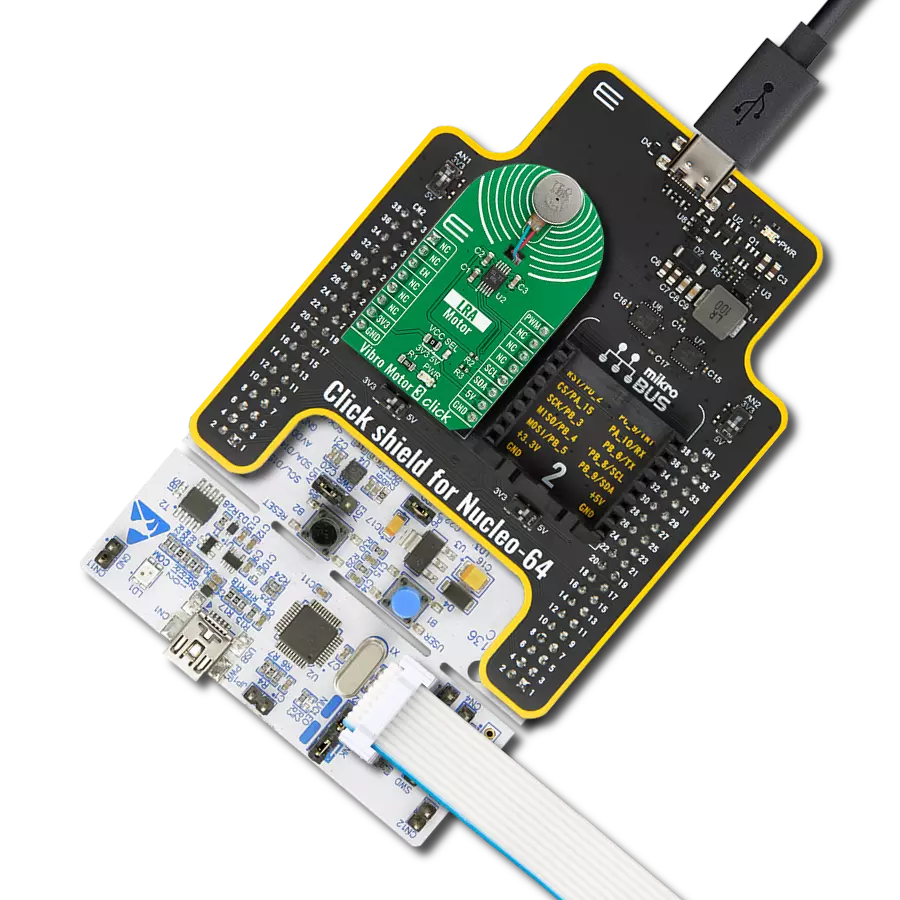
Vibro Motor 3 Click is based on the G0832022D, a coin-sized linear resonant actuator that generates vibration/haptic feedback in the Z plane, perpendicular to the motor's surface from Jinlong Machinery & Electronics, Inc. The G0832022D draws only 19mA at 0.6V while producing a G force of 0.55 GRMS and makes an excellent choice for applications requiring crisp haptic feedback and low power consumption. For haptic feedback applications, fast rise and fall times are critical for achieving the optimal user experience. Driven by the DRV2605, a flexible Haptic/Vibra driver from Texas Instruments, this Click board™ is designed to provide highly flexible haptic control over a standard I2C 2-Wire interface with a maximum clock frequency of 400kHz. It possesses an enabling function, routed on the CS pin
of the mikroBUS™ socket labeled as the EN, and comes up with an extensive integrated library of over 100 licensed effects that eliminates the need to design haptics waveforms. It also contains a smart-loop architecture, which allows effortless auto resonant drive for LRA motor drive. This feedback provides automatic overdrive and braking, which creates a simplified input waveform paradigm, reliable motor control, and consistent motor performance. The DRV2605 can also operate in the PWM Mode and accept the PWM signal from the PWM pin of the mikroBUS™ socket. In this mode, the DRV2605 device drives the actuator continuously until the user sets the DRV2605 to a Standby Mode or enters another interface mode. In PWM Mode, the vibration strength is controlled by the duty cycle, and
for the LRA motor, the DRV2605 automatically tracks the resonance frequency unless the LRA_OPEN_LOOP bit in register 0x1D is set. If the LRA_OPEN_LOOP bit is set, then the LRA motor is driven according to the frequency of the PWM input signal. More information about the operating modes of the DRV2605 can be found in the attached datasheet. This Click board™ can operate with either 3.3V or 5V logic voltage levels selected via the VCC SEL jumper. This way, both 3.3V and 5V capable MCUs can use the communication lines properly. Also, this Click board™ comes equipped with a library containing easy-to-use functions and an example code that can be used as a reference for further development.


Features overview
Development board
Arduino UNO is a versatile microcontroller board built around the ATmega328P chip. It offers extensive connectivity options for various projects, featuring 14 digital input/output pins, six of which are PWM-capable, along with six analog inputs. Its core components include a 16MHz ceramic resonator, a USB connection, a power jack, an
ICSP header, and a reset button, providing everything necessary to power and program the board. The Uno is ready to go, whether connected to a computer via USB or powered by an AC-to-DC adapter or battery. As the first USB Arduino board, it serves as the benchmark for the Arduino platform, with "Uno" symbolizing its status as the
first in a series. This name choice, meaning "one" in Italian, commemorates the launch of Arduino Software (IDE) 1.0. Initially introduced alongside version 1.0 of the Arduino Software (IDE), the Uno has since become the foundational model for subsequent Arduino releases, embodying the platform's evolution.

Microcontroller Overview
MCU Card / MCU

Architecture
AVR
MCU Memory (KB)
32
Silicon Vendor
Microchip
Pin count
28
RAM (Bytes)
2048
You complete me!
Accessories
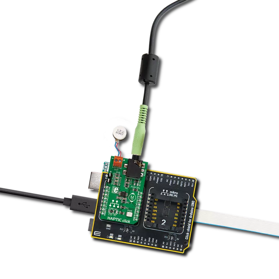
Click Shield for Arduino UNO has two proprietary mikroBUS™ sockets, allowing all the Click board™ devices to be interfaced with the Arduino UNO board without effort. The Arduino Uno, a microcontroller board based on the ATmega328P, provides an affordable and flexible way for users to try out new concepts and build prototypes with the ATmega328P microcontroller from various combinations of performance, power consumption, and features. The Arduino Uno has 14 digital input/output pins (of which six can be used as PWM outputs), six analog inputs, a 16 MHz ceramic resonator (CSTCE16M0V53-R0), a USB connection, a power jack, an ICSP header, and reset button. Most of the ATmega328P microcontroller pins are brought to the IO pins on the left and right edge of the board, which are then connected to two existing mikroBUS™ sockets. This Click Shield also has several switches that perform functions such as selecting the logic levels of analog signals on mikroBUS™ sockets and selecting logic voltage levels of the mikroBUS™ sockets themselves. Besides, the user is offered the possibility of using any Click board™ with the help of existing bidirectional level-shifting voltage translators, regardless of whether the Click board™ operates at a 3.3V or 5V logic voltage level. Once you connect the Arduino UNO board with our Click Shield for Arduino UNO, you can access hundreds of Click boards™, working with 3.3V or 5V logic voltage levels.

Used MCU Pins
mikroBUS™ mapper
Take a closer look
Click board™ Schematic

Step by step
Project assembly

Start by selecting your development board and Click board™. Begin with the Arduino UNO Rev3 as your development board.


Software Support
Library Description
This library contains API for Vibro Motor 3 Click driver.
Key functions:
vibromotor3_set_duty_cycle- Vibro Motor 3 sets PWM duty cyclevibromotor3_enable- Enable the device functionvibromotor3_write_byte- Generic write the byte of data function
Open Source
Code example
The complete application code and a ready-to-use project are available through the NECTO Studio Package Manager for direct installation in the NECTO Studio. The application code can also be found on the MIKROE GitHub account.
/*!
 * @file main.c
 * @brief VibroMotor3 Click example
 *
 * # Description
 * This example shows the capabilities of the Vibro Motor 3 Click board
 *
 * The demo application is composed of two sections :
 *
 * ## Application Init
 * Initalizes I2C driver, PWM driver and configures Vibro Motor 3 Click board.
 *
 * ## Application Task
 * Changing duty cycle applied in order to get different vibrations.
 *
 * @author Stefan Ilic
 *
 */

#include "board.h"
#include "log.h"
#include "vibromotor3.h"

static vibromotor3_t vibromotor3;
static log_t logger;

static float pwm_max_duty = 1;
static float pwm_duty_cycle = 0;


void application_init ( void ) {
    log_cfg_t log_cfg;  /**< Logger config object. */
    vibromotor3_cfg_t vibromotor3_cfg;  /**< Click config object. */

    /**
     * Logger initialization.
     * Default baud rate: 115200
     * Default log level: LOG_LEVEL_DEBUG
     * @note If USB_UART_RX and USB_UART_TX
     * are defined as HAL_PIN_NC, you will
     * need to define them manually for log to work.
     * See @b LOG_MAP_USB_UART macro definition for detailed explanation.
     */
    LOG_MAP_USB_UART( log_cfg );
    log_init( &logger, &log_cfg );
    log_info( &logger, " Application Init " );

    // Click initialization.
    vibromotor3_cfg_setup( &vibromotor3_cfg );
    VIBROMOTOR3_MAP_MIKROBUS( vibromotor3_cfg, MIKROBUS_1 );
    err_t init_flag = vibromotor3_init( &vibromotor3, &vibromotor3_cfg );
    if ( I2C_MASTER_ERROR == init_flag || PWM_ERROR == init_flag ) {
        log_error( &logger, " Application Init Error. " );
        log_info( &logger, " Please, run program again... " );

        for ( ; ; );
    }
    vibromotor3_enable( &vibromotor3, VIBROMOTOR3_PROPERTY_ENABLE );
    Delay_ms ( 100 );

    vibromotor3_soft_rst( &vibromotor3 );
    Delay_ms ( 100 );

    vibromotor3_default_cfg( &vibromotor3 );
    Delay_ms ( 100 );

    vibromotor3_set_duty_cycle( &vibromotor3, 0.0 );
    vibromotor3_pwm_start( &vibromotor3 );
    Delay_ms ( 100 );

    log_info( &logger, " Application Task " );
    Delay_ms ( 100 );
}

void application_task ( void ) {
    static int8_t duty_cnt = 1;
    static int8_t duty_inc = 1;
    float duty = duty_cnt / 10.0;

    vibromotor3_set_duty_cycle ( &vibromotor3, duty );
    log_printf( &logger, "> Duty: %d%%\r\n", ( uint16_t )( duty_cnt * 10 ) );

    Delay_ms ( 500 );

    if ( 10 == duty_cnt ) {
        duty_inc = -1;
    } else if ( 0 == duty_cnt ) {
        duty_inc = 1;
    }
    duty_cnt += duty_inc;
}

int main ( void )
{
    /* Do not remove this line or clock might not be set correctly. */
    #ifdef PREINIT_SUPPORTED
    preinit();
    #endif

    application_init( );

    for ( ; ; )
    {
        application_task( );
    }

    return 0;
}

// ------------------------------------------------------------------------ END
Additional Support
Resources
Category:Haptic