Enhance user experiences with advanced ERM motor control based on C1026B002F and ATmega328P
Sync and thrive!

Published Feb 14, 2024
Click board™
Vibro Motor Click
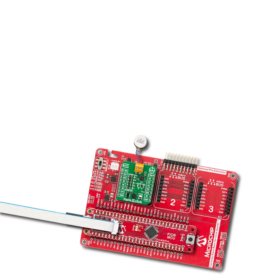
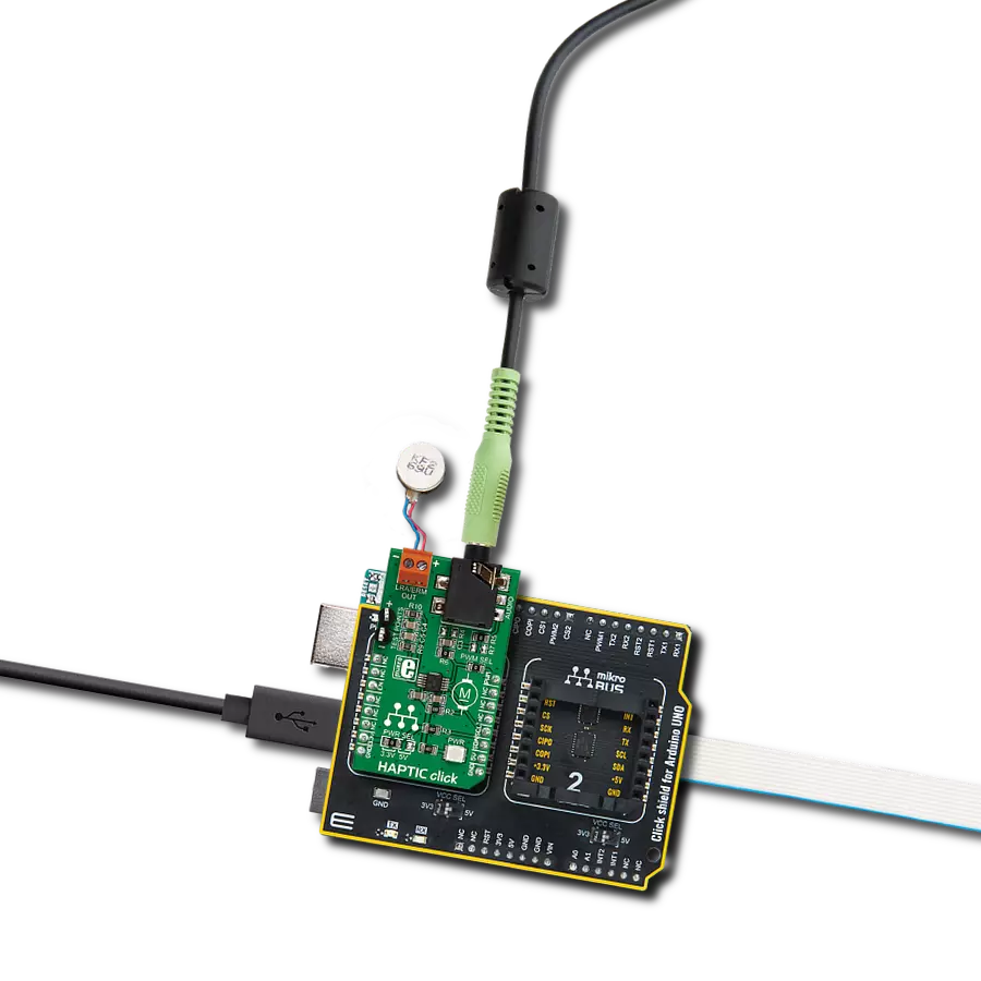
Dev. board
Arduino UNO Rev3
Compiler
NECTO Studio
MCU
ATmega328P
In today's dynamic landscape of vibrational applications, our solution aims to simplify motor control and enhance vibrational experiences, offering a user-friendly way to manage ERM motors
A
A
Hardware Overview
How does it work?
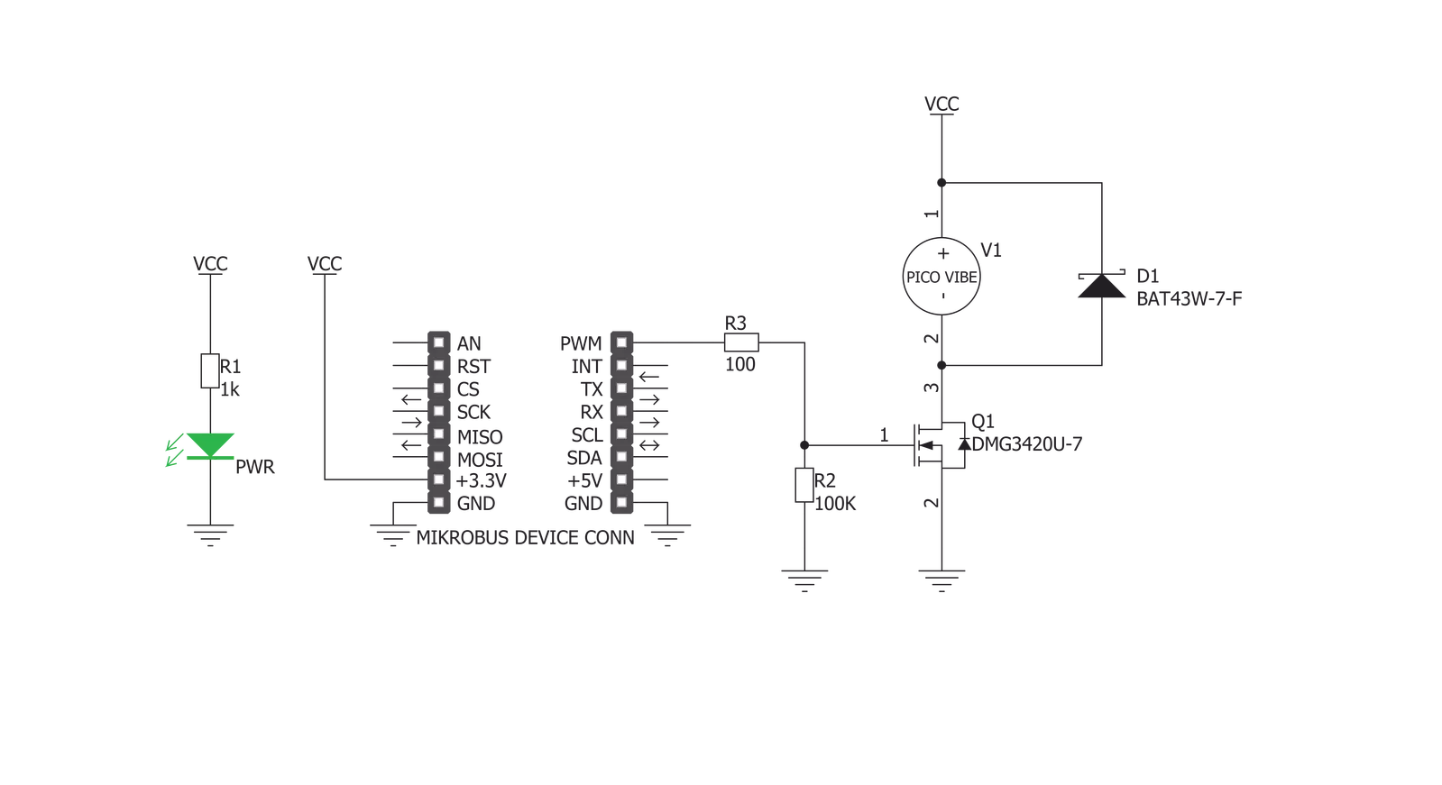
Vibro Motor Click is based on the C1026B002F, a compact-size Eccentric Rotating Mass (ERM) motor. This type of motor is often used for haptic feedback on many small handheld devices, such as cellphones, pagers, RFID scanners, and similar devices. This motor contains a small eccentric weight on its rotor, so it also produces a vibration effect while rotating. This kind of motor is sometimes called a coin motor due to its shape. Besides the vibration motor, the click is also equipped with the DMG3420U, a small MOSFET used to drive the motor. The Vibro Motor click is ideal for adding simple, one-pin-driven haptic feedback on any design. The circuit also contains
a protection diode, which protects the transistor from the reverse voltage since the motor represents an inductive load, and turning off its current can produce a kickback voltage that can damage the transistor. The gate of the MOSFET is driven by the PWM signal, routed through the PWM pin of the mikroBUS™. The PWM signal toggles the gate of the MOSFET with pulses of a certain width. As a result, the current through the motor is varied depending on the pulse width of the PWM signal, which directly affects the speed of the motor, effectively controlling the vibration force that way. The small, eccentric weight attached to the rotor of the coin motor generates
the centrifugal force while it rotates, which in turn results in the wobbling effect of the motor itself. The faster the rotation is, the bigger the force gets. Controlling the motor speed allows for the vibration intensity to be controlled. This Click board™ can be operated only with a 3.3V logic voltage level. The board must perform appropriate logic voltage level conversion before using MCUs with different logic levels. Also, it comes equipped with a library containing functions and an example code that can be used as a reference for further development.


Features overview
Development board
Arduino UNO is a versatile microcontroller board built around the ATmega328P chip. It offers extensive connectivity options for various projects, featuring 14 digital input/output pins, six of which are PWM-capable, along with six analog inputs. Its core components include a 16MHz ceramic resonator, a USB connection, a power jack, an
ICSP header, and a reset button, providing everything necessary to power and program the board. The Uno is ready to go, whether connected to a computer via USB or powered by an AC-to-DC adapter or battery. As the first USB Arduino board, it serves as the benchmark for the Arduino platform, with "Uno" symbolizing its status as the
first in a series. This name choice, meaning "one" in Italian, commemorates the launch of Arduino Software (IDE) 1.0. Initially introduced alongside version 1.0 of the Arduino Software (IDE), the Uno has since become the foundational model for subsequent Arduino releases, embodying the platform's evolution.

Microcontroller Overview
MCU Card / MCU

Architecture
AVR
MCU Memory (KB)
32
Silicon Vendor
Microchip
Pin count
28
RAM (Bytes)
2048
You complete me!
Accessories
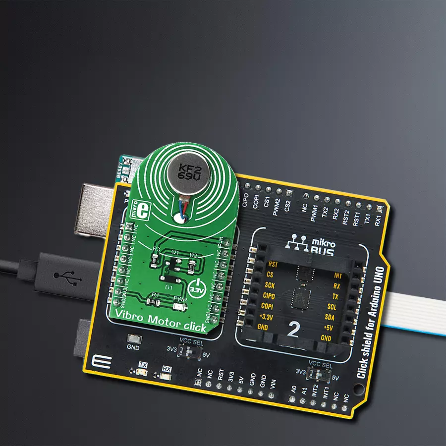
Click Shield for Arduino UNO has two proprietary mikroBUS™ sockets, allowing all the Click board™ devices to be interfaced with the Arduino UNO board without effort. The Arduino Uno, a microcontroller board based on the ATmega328P, provides an affordable and flexible way for users to try out new concepts and build prototypes with the ATmega328P microcontroller from various combinations of performance, power consumption, and features. The Arduino Uno has 14 digital input/output pins (of which six can be used as PWM outputs), six analog inputs, a 16 MHz ceramic resonator (CSTCE16M0V53-R0), a USB connection, a power jack, an ICSP header, and reset button. Most of the ATmega328P microcontroller pins are brought to the IO pins on the left and right edge of the board, which are then connected to two existing mikroBUS™ sockets. This Click Shield also has several switches that perform functions such as selecting the logic levels of analog signals on mikroBUS™ sockets and selecting logic voltage levels of the mikroBUS™ sockets themselves. Besides, the user is offered the possibility of using any Click board™ with the help of existing bidirectional level-shifting voltage translators, regardless of whether the Click board™ operates at a 3.3V or 5V logic voltage level. Once you connect the Arduino UNO board with our Click Shield for Arduino UNO, you can access hundreds of Click boards™, working with 3.3V or 5V logic voltage levels.

Used MCU Pins
mikroBUS™ mapper
Take a closer look
Click board™ Schematic
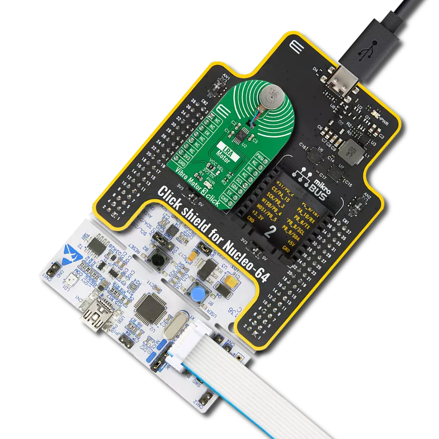
Step by step
Project assembly

Start by selecting your development board and Click board™. Begin with the Arduino UNO Rev3 as your development board.


Software Support
Library Description
This library contains API for Vibro Motor Click driver.
Key functions:
vibromotor_set_duty_cycle- This function sets the PWM duty cycle in percentages ( Range[ 0..1 ] )vibromotor_pwm_stop- This function stops the PWM moudle outputvibromotor_pwm_start- This function starts the PWM moudle output.
Open Source
Code example
The complete application code and a ready-to-use project are available through the NECTO Studio Package Manager for direct installation in the NECTO Studio. The application code can also be found on the MIKROE GitHub account.
/*!
 * @file main.c
 * @brief VibroMotor Click example
 *
 * # Description
 * This application contorl the speed of vibro motor.
 *
 * The demo application is composed of two sections :
 *
 * ## Application Init
 * Initializes GPIO driver and PWM.
 * Configures PWM to 5kHz frequency, calculates maximum duty ratio and starts PWM
 * with duty ratio value 0.
 *
 * ## Application Task
 * Allows user to enter desired command to control
 * Vibro Motor Click board.
 *
 * @author Stefan Ilic
 *
 */

#include "board.h"
#include "log.h"
#include "vibromotor.h"


static vibromotor_t vibromotor;
static log_t logger;

void application_init ( void ) {
    log_cfg_t log_cfg;  /**< Logger config object. */
    vibromotor_cfg_t vibromotor_cfg;  /**< Click config object. */

    /**
     * Logger initialization.
     * Default baud rate: 115200
     * Default log level: LOG_LEVEL_DEBUG
     * @note If USB_UART_RX and USB_UART_TX
     * are defined as HAL_PIN_NC, you will
     * need to define them manually for log to work.
     * See @b LOG_MAP_USB_UART macro definition for detailed explanation.
     */
    LOG_MAP_USB_UART( log_cfg );
    log_init( &logger, &log_cfg );
    log_info( &logger, " Application Init " );

    // Click initialization.

    vibromotor_cfg_setup( &vibromotor_cfg );
    VIBROMOTOR_MAP_MIKROBUS( vibromotor_cfg, MIKROBUS_1 );
    err_t init_flag  = vibromotor_init( &vibromotor, &vibromotor_cfg );
    if ( PWM_ERROR == init_flag ) {
        log_error( &logger, " Application Init Error. " );
        log_info( &logger, " Please, run program again... " );

        for ( ; ; );
    }

    vibromotor_set_duty_cycle ( &vibromotor, 0.0 );
    vibromotor_pwm_start( &vibromotor );

    log_info( &logger, " Application Task " );
}

void application_task ( void ) {
    static int8_t duty_cnt = 1;
    static int8_t duty_inc = 1;
    float duty = duty_cnt / 10.0;

    vibromotor_set_duty_cycle ( &vibromotor, duty );
    log_printf( &logger, "> Duty: %d%%\r\n", ( uint16_t )( duty_cnt * 10 ) );

    Delay_ms ( 500 );

    if ( 10 == duty_cnt ) {
        duty_inc = -1;
    } else if ( 0 == duty_cnt ) {
        duty_inc = 1;
    }
    duty_cnt += duty_inc;
}

int main ( void )
{
    /* Do not remove this line or clock might not be set correctly. */
    #ifdef PREINIT_SUPPORTED
    preinit();
    #endif

    application_init( );

    for ( ; ; )
    {
        application_task( );
    }

    return 0;
}

// ------------------------------------------------------------------------ END
Additional Support
Resources
Category:Haptic