Make a wireless connection without any trouble with XB8X-DMUS-001 and ATmega328P
Ready, set, connect!
Published Feb 14, 2024
Click board™
XBee 3 Click
Dev. board
Arduino UNO Rev3
Compiler
NECTO Studio
MCU
ATmega328P
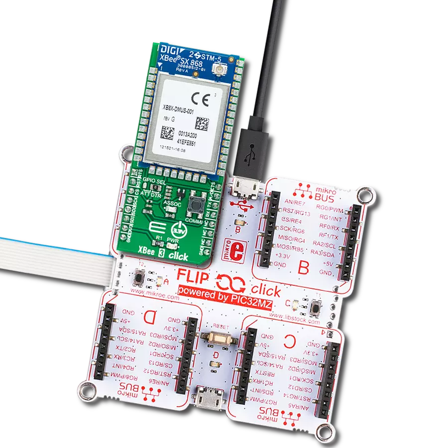
Secure and reliable wireless connectivity for various M2M and IoT devices
A
A
Hardware Overview
How does it work?
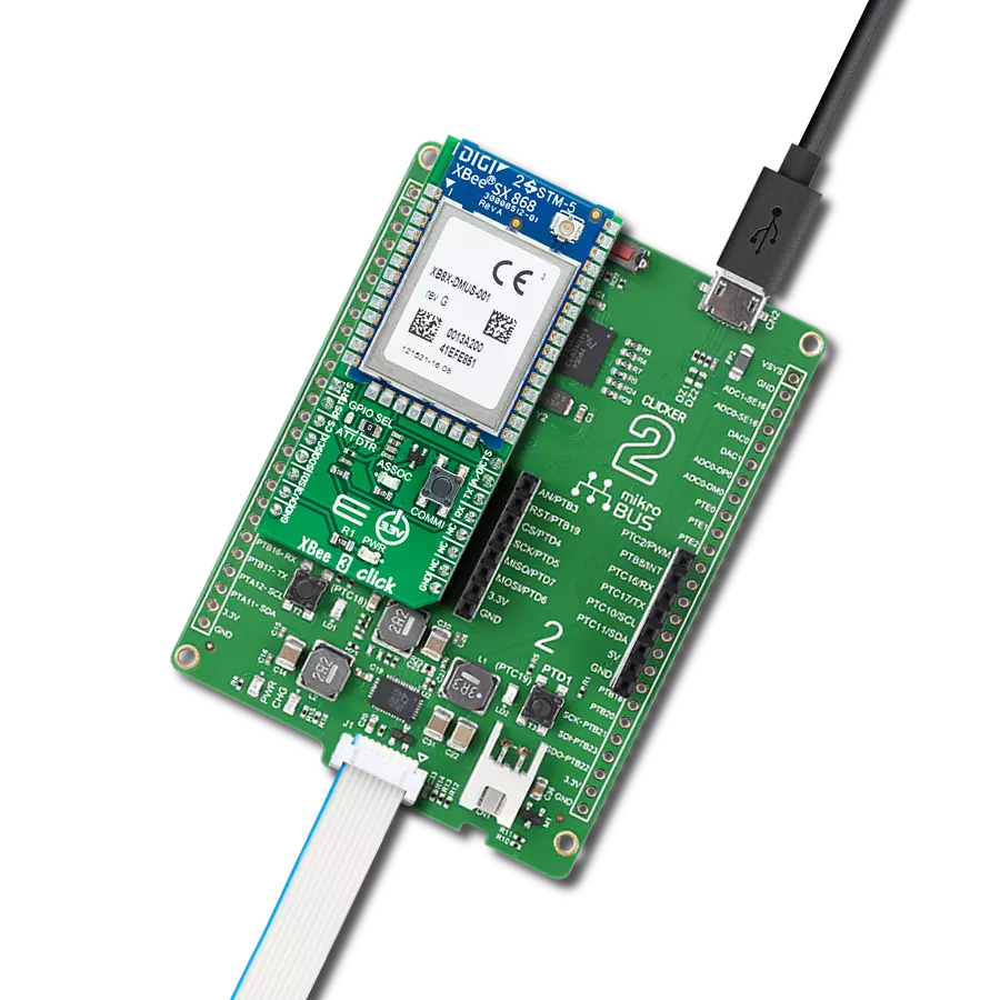
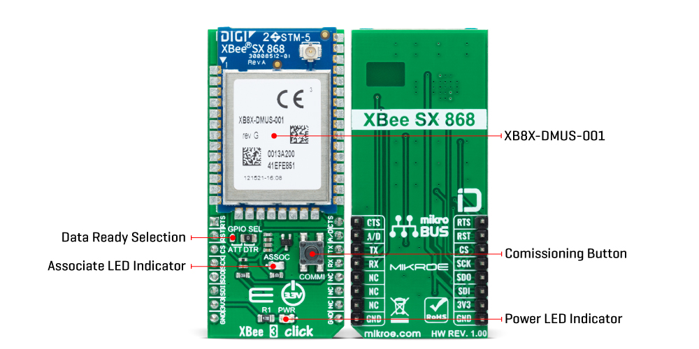
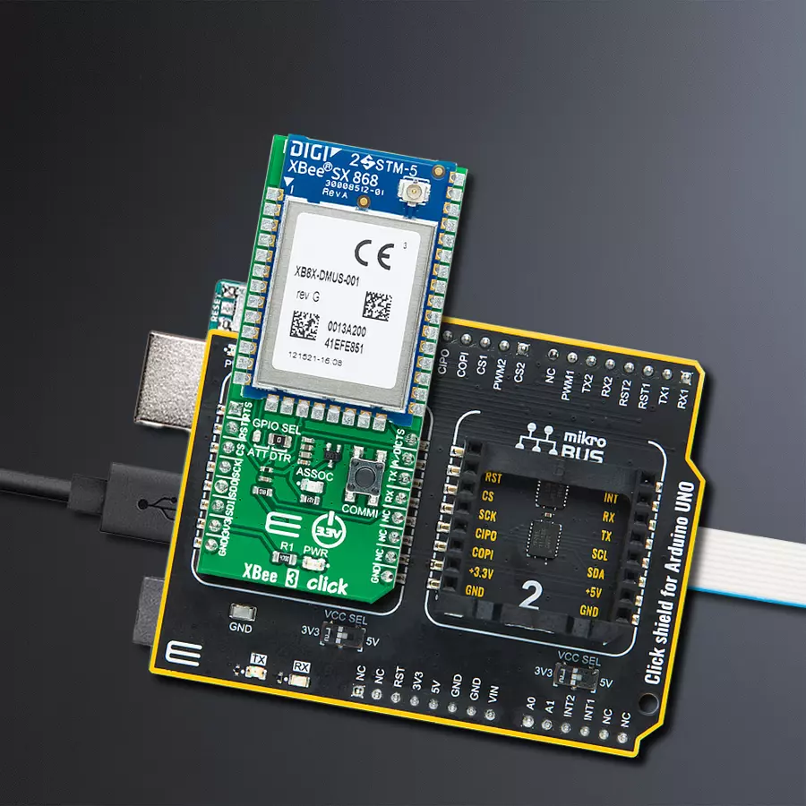
XBee 3 Click is based on the XB8X-DMUS-001, a Digi XBee® CE/RED certified RF module suitable for mission-critical wireless applications from Digi International. The XB8X-DMUS-001 can run a proprietary DigiMesh® or point-to-multipoint networking protocol utilizing a low-power Silicon Labs MCU and an ADF7023 transceiver with an integrated SAW filter offering industry-leading interference blocking. It also supports low-power sleeping nodes and has an RF line-of-sight range of up to 14km (rural range line of sight) in a combination of coverage, data redundancy, and data reliability. The XB8X-DMUS-001 module is pre-certified for use in European countries. Operating between 863MHz and 870MHz (868MHz), it allows use in several regions, including approved European countries. It also leverages surrounding frequencies for LBT+AFA (Listen-Before-Talk and Adaptive-Frequency-Agility), significantly reducing interference by listening to the radio environment before any transmission starts and automatically shifting to a new channel when interference is
detected. This Click board™ comes with a configurable host interface allowing communication with MCU using the chosen interface. The XB8X-DMUS-001 can communicate with MCU using the UART interface with commonly used UART RX, TX, and hardware flow control pins UART CTS and RTS (Clear to Send and Ready to Send) or using the SPI interface (XBee module will work as an SPI-slave only). In the case of the SPI interface, the users can use it to configure the module and write the library by themselves. The XBee 3 Click is associated with many other features, such as the reset function and the possibility of visual and digital indicators. An active-low reset signal routed on the RST pin of the mikroBUS™ socket activates a hardware reset of the system, while a yellow LED indicator marked as ASSOC represents a visual indication of the module's connection to the network. If the LED is constantly on, it means that the module is not connected to the mobile network, while the standard flashing of the LED represents the normal operating mode. The A/D pin of the mikroBUS™ socket
represents a type of interrupt whose function can be selected by positioning an onboard SMD jumper to an appropriate position labeled as DTR or ATT. DTR position is a "Data terminal ready" function used to tell the XBee module that the host MCU is ready to communicate, while the ATT position (SPI Attention) represents an indicator for the SPI interface whenever the XBee module has data for the host MCU. In addition, the board also has a commissioning pushbutton marked as COMMI, which, combined with an ASSOC LED, provides various simple functions to aid in deploying devices in a network. This Click board™ can only be operated from a 3.3V logic voltage level. Therefore, the board must perform appropriate logic voltage conversion before using MCUs with different logic levels. However, the Click board™ comes equipped with a library containing functions and an example code that can be used as a reference for further development.
Features overview
Development board
Arduino UNO is a versatile microcontroller board built around the ATmega328P chip. It offers extensive connectivity options for various projects, featuring 14 digital input/output pins, six of which are PWM-capable, along with six analog inputs. Its core components include a 16MHz ceramic resonator, a USB connection, a power jack, an
ICSP header, and a reset button, providing everything necessary to power and program the board. The Uno is ready to go, whether connected to a computer via USB or powered by an AC-to-DC adapter or battery. As the first USB Arduino board, it serves as the benchmark for the Arduino platform, with "Uno" symbolizing its status as the
first in a series. This name choice, meaning "one" in Italian, commemorates the launch of Arduino Software (IDE) 1.0. Initially introduced alongside version 1.0 of the Arduino Software (IDE), the Uno has since become the foundational model for subsequent Arduino releases, embodying the platform's evolution.

Microcontroller Overview
MCU Card / MCU

Architecture
AVR
MCU Memory (KB)
32
Silicon Vendor
Microchip
Pin count
28
RAM (Bytes)
2048
You complete me!
Accessories
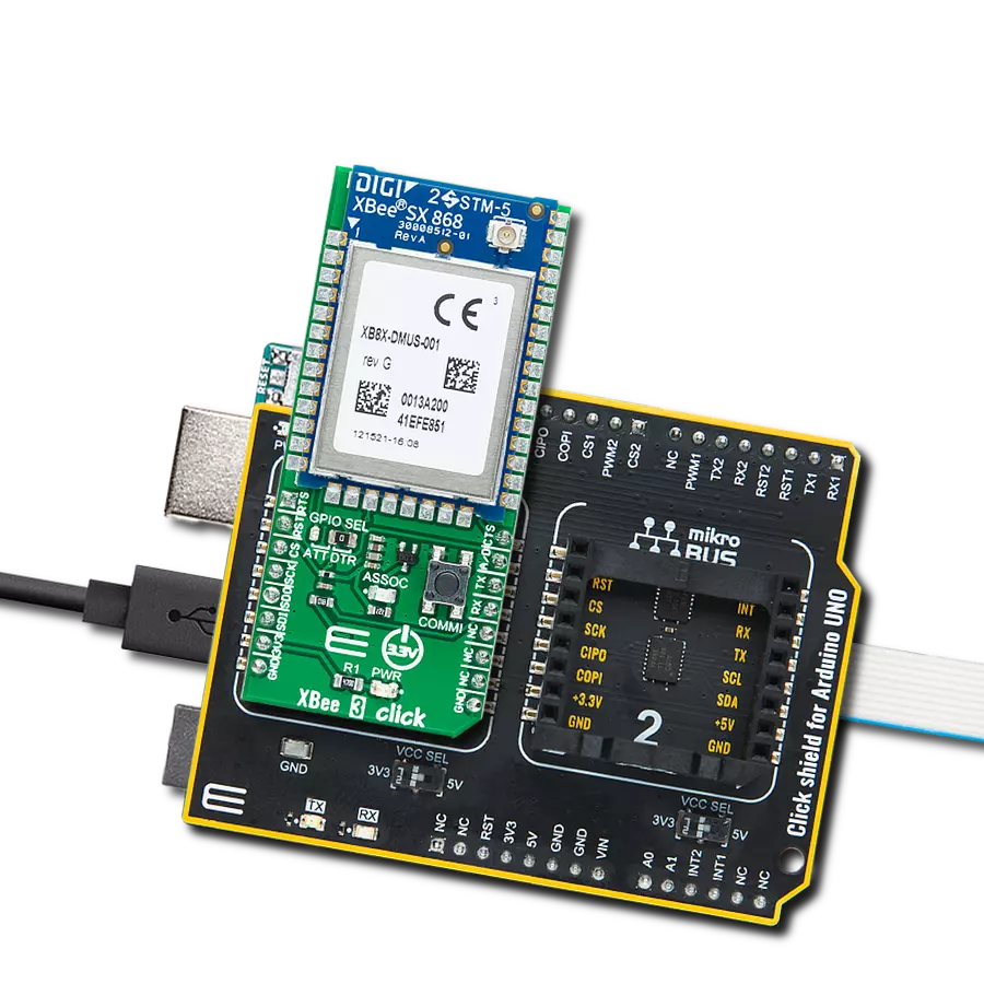
Click Shield for Arduino UNO has two proprietary mikroBUS™ sockets, allowing all the Click board™ devices to be interfaced with the Arduino UNO board without effort. The Arduino Uno, a microcontroller board based on the ATmega328P, provides an affordable and flexible way for users to try out new concepts and build prototypes with the ATmega328P microcontroller from various combinations of performance, power consumption, and features. The Arduino Uno has 14 digital input/output pins (of which six can be used as PWM outputs), six analog inputs, a 16 MHz ceramic resonator (CSTCE16M0V53-R0), a USB connection, a power jack, an ICSP header, and reset button. Most of the ATmega328P microcontroller pins are brought to the IO pins on the left and right edge of the board, which are then connected to two existing mikroBUS™ sockets. This Click Shield also has several switches that perform functions such as selecting the logic levels of analog signals on mikroBUS™ sockets and selecting logic voltage levels of the mikroBUS™ sockets themselves. Besides, the user is offered the possibility of using any Click board™ with the help of existing bidirectional level-shifting voltage translators, regardless of whether the Click board™ operates at a 3.3V or 5V logic voltage level. Once you connect the Arduino UNO board with our Click Shield for Arduino UNO, you can access hundreds of Click boards™, working with 3.3V or 5V logic voltage levels.

Used MCU Pins
mikroBUS™ mapper
Take a closer look
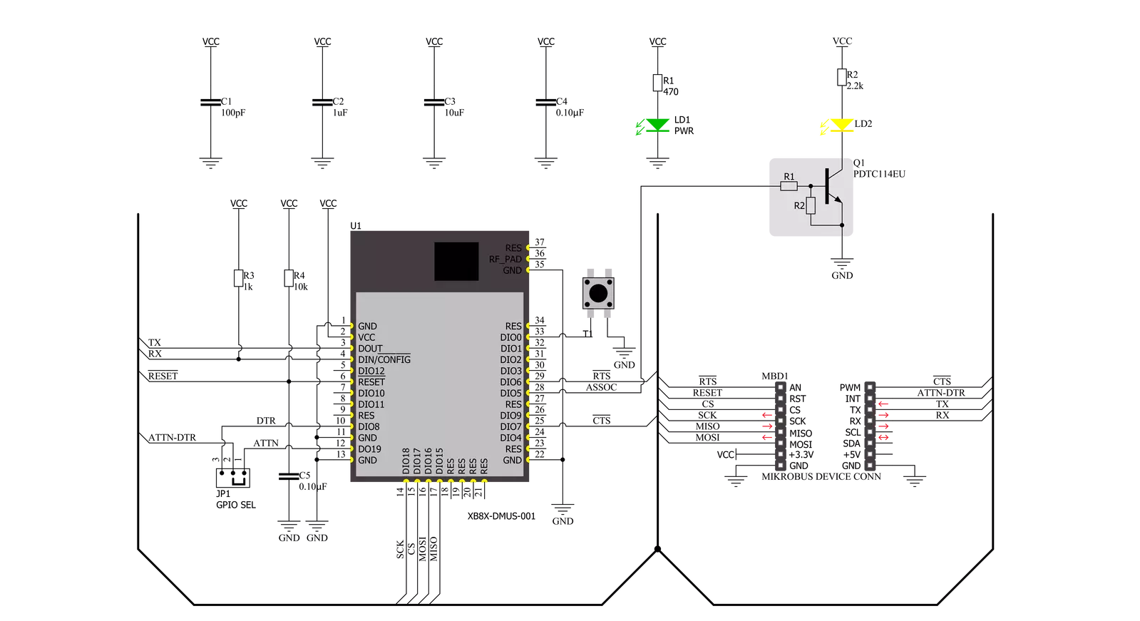
Click board™ Schematic
Step by step
Project assembly

Start by selecting your development board and Click board™. Begin with the Arduino UNO Rev3 as your development board.


Software Support
Library Description
This library contains API for XBee 3 Click driver.
Key functions:
xbee3_get_serial_numberThis function sends a get serial number command.xbee3_set_device_nameThis function sets the device name (node identifier).xbee3_set_destination_addressThis function sets the destination address high and low bytes.
Open Source
Code example
The complete application code and a ready-to-use project are available through the NECTO Studio Package Manager for direct installation in the NECTO Studio. The application code can also be found on the MIKROE GitHub account.
/*!
 * @file main.c
 * @brief XBEE 3 Click Example.
 *
 * # Description
 * This example demonstrates the use of an XBEE 3 Click board by showing
 * the communication between the two Click boards configured in transparent mode.
 *
 * The demo application is composed of two sections :
 *
 * ## Application Init
 * Initializes the driver and configures the Click board by performing a factory reset,
 * and setting the device name, destination address, and api mode to transparent.
 *
 * ## Application Task
 * Depending on the selected application mode, it reads all the received data or
 * sends the desired message every 3 seconds.
 *
 * ## Additional Function
 * - static void xbee3_clear_app_buf ( void )
 * - static err_t xbee3_process ( void )
 * - static err_t xbee3_display_rsp ( uint16_t timeout )
 *
 * @author Stefan Filipovic
 *
 */

#include "board.h"
#include "log.h"
#include "xbee3.h"

// Device name (Node identifier).
#define DEVICE_NAME                 "XBEE 3 Click"

// Enter here the specific serial number high and low bytes of the remote device as a hex string or
// leave it set to broadcast addresses for forwarding messages to all devices
#define DESTINATION_ADDRESS_HIGH    XBEE3_BROADCAST_DEST_ADDRESS_HIGH
#define DESTINATION_ADDRESS_LOW     XBEE3_BROADCAST_DEST_ADDRESS_LOW

// Comment out the line below in order to switch the application mode to receiver
#define DEMO_APP_TRANSMITTER

// Text message to send in the transmitter application mode
#define DEMO_TEXT_MESSAGE           "MikroE - XBEE 3 Click board\r\n"

// Application process buffer size
#define PROCESS_BUFFER_SIZE         200

static xbee3_t xbee3;
static log_t logger;

static char app_buf[ PROCESS_BUFFER_SIZE ] = { 0 };
static int32_t app_buf_len = 0;
static int32_t app_buf_cnt = 0;

/**
 * @brief XBEE 3 clearing application buffer.
 * @details This function clears memory of application buffer and reset its length and counter.
 * @note None.
 */
static void xbee3_clear_app_buf ( void );

/**
 * @brief XBEE 3 data reading function.
 * @details This function reads data from device and concatenates data to application buffer.
 * @return @li @c  0 - Read some data.
 *         @li @c -1 - Nothing is read.
 *         @li @c -2 - Application buffer overflow.
 * See #err_t definition for detailed explanation.
 * @note None.
 */
static err_t xbee3_process ( void );

/**
 * @brief XBEE 3 display response function.
 * @details This function reads data from device until it sends OK or ERROR message or until
 * it exceeds the timeout value.
 * @param[in] timeout : Timeout value in miliseconds.
 * @return @li @c  0 - Read some data.
 *         @li @c -1 - Nothing is read.
 * See #err_t definition for detailed explanation.
 * @note None.
 */
static err_t xbee3_display_rsp ( uint16_t timeout );

void application_init ( void )
{
    log_cfg_t log_cfg;  /**< Logger config object. */
    xbee3_cfg_t xbee3_cfg;  /**< Click config object. */

    /**
     * Logger initialization.
     * Default baud rate: 115200
     * Default log level: LOG_LEVEL_DEBUG
     * @note If USB_UART_RX and USB_UART_TX
     * are defined as HAL_PIN_NC, you will
     * need to define them manually for log to work.
     * See @b LOG_MAP_USB_UART macro definition for detailed explanation.
     */
    LOG_MAP_USB_UART( log_cfg );
    log_init( &logger, &log_cfg );
    log_info( &logger, " Application Init " );

    // Click initialization.
    xbee3_cfg_setup( &xbee3_cfg );
    XBEE3_MAP_MIKROBUS( xbee3_cfg, MIKROBUS_1 );
    if ( UART_ERROR == xbee3_init( &xbee3, &xbee3_cfg ) )
    {
        log_error( &logger, " Communication init." );
        for ( ; ; );
    }

    xbee3_hw_reset ( &xbee3 );
    xbee3_process( );
    xbee3_clear_app_buf( );

    log_printf( &logger, " - Enter command mode -\r\n" );
    xbee3_enter_command_mode ( &xbee3 );
    Delay_ms ( 100 );
    xbee3_display_rsp ( 1000 );

    log_printf( &logger, " - Factory Reset -\r\n" );
    xbee3_factory_reset ( &xbee3 );
    Delay_ms ( 100 );
    xbee3_display_rsp ( 1000 );

    log_printf( &logger, " - Get serial number -\r\n" );
    xbee3_get_serial_number ( &xbee3 );
    Delay_ms ( 100 );
    xbee3_display_rsp ( 1000 );

    log_printf( &logger, " - Set Device Name -\r\n" );
    xbee3_set_device_name ( &xbee3, DEVICE_NAME );
    Delay_ms ( 100 );
    xbee3_display_rsp ( 1000 );

    log_printf( &logger, " - Set Destination Address -\r\n" );
    xbee3_set_destination_address ( &xbee3, DESTINATION_ADDRESS_HIGH, DESTINATION_ADDRESS_LOW );
    Delay_ms ( 100 );
    xbee3_display_rsp ( 1000 );

    log_printf( &logger, " - Set API mode -\r\n" );
    xbee3_set_api_mode ( &xbee3, XBEE3_MODE_TRANSPARENT );
    Delay_ms ( 100 );
    xbee3_display_rsp ( 1000 );

    log_printf( &logger, " - Apply changes -\r\n" );
    xbee3_apply_changes ( &xbee3 );
    Delay_ms ( 100 );
    xbee3_display_rsp ( 1000 );

    log_printf( &logger, " - Save changes -\r\n" );
    xbee3_save_changes ( &xbee3 );
    Delay_ms ( 100 );
    xbee3_display_rsp ( 1000 );

    log_printf( &logger, " - Exit command mode -\r\n" );
    xbee3_exit_command_mode ( &xbee3 );
    Delay_ms ( 100 );
    xbee3_display_rsp ( 1000 );

    app_buf_len = 0;
    app_buf_cnt = 0;

#ifdef DEMO_APP_TRANSMITTER
    log_printf( &logger, " Application Mode: Transmitter\r\n" );
#else
    log_printf( &logger, " Application Mode: Receiver\r\n" );
#endif

    log_info( &logger, " Application Task " );
}

void application_task ( void )
{
#ifdef DEMO_APP_TRANSMITTER
    xbee3_generic_write( &xbee3, DEMO_TEXT_MESSAGE, strlen( DEMO_TEXT_MESSAGE ) );
    log_printf( &logger, "%s", ( char * ) DEMO_TEXT_MESSAGE );
    Delay_ms ( 1000 );
    Delay_ms ( 1000 );
    Delay_ms ( 1000 );
#else
    xbee3_process( );
    if ( app_buf_len > 0 )
    {
        log_printf( &logger, "%s", app_buf );
        xbee3_clear_app_buf(  );
    }
#endif
}

int main ( void )
{
    /* Do not remove this line or clock might not be set correctly. */
    #ifdef PREINIT_SUPPORTED
    preinit();
    #endif

    application_init( );

    for ( ; ; )
    {
        application_task( );
    }

    return 0;
}

static void xbee3_clear_app_buf ( void )
{
    memset( app_buf, 0, app_buf_len );
    app_buf_len = 0;
    app_buf_cnt = 0;
}

static err_t xbee3_process ( void )
{
    int32_t rx_size;
    char rx_buf[ PROCESS_BUFFER_SIZE ] = { 0 };
    rx_size = xbee3_generic_read( &xbee3, rx_buf, PROCESS_BUFFER_SIZE );
    if ( rx_size > 0 )
    {
        int32_t buf_cnt = 0;
        if ( ( app_buf_len + rx_size ) > PROCESS_BUFFER_SIZE )
        {
            xbee3_clear_app_buf(  );
            return XBEE3_ERROR;
        }
        else
        {
            buf_cnt = app_buf_len;
            app_buf_len += rx_size;
        }
        for ( int32_t rx_cnt = 0; rx_cnt < rx_size; rx_cnt++ )
        {
            if ( rx_buf[ rx_cnt ] != 0 )
            {
                app_buf[ ( buf_cnt + rx_cnt ) ] = rx_buf[ rx_cnt ];
            }
            else
            {
                app_buf_len--;
                buf_cnt--;
            }
        }
        return XBEE3_OK;
    }
    return XBEE3_ERROR;
}

static err_t xbee3_display_rsp ( uint16_t timeout )
{
    uint16_t timeout_cnt = 0;
    xbee3_process ( );
    while ( ( 0 == strstr( app_buf, XBEE3_RSP_OK ) ) &&
            ( 0 == strstr( app_buf, XBEE3_RSP_ERROR ) ) &&
            ( timeout_cnt++ < timeout ) )
    {
        xbee3_process ( );
        Delay_ms ( 1 );
    }
    if ( app_buf_len > 0 )
    {
        for ( int32_t buf_cnt = 0; buf_cnt < app_buf_len; buf_cnt++ )
        {
            log_printf( &logger, "%c", app_buf[ buf_cnt ] );
        }
        xbee3_clear_app_buf ( );
        log_printf( &logger, "--------------------------------\r\n" );
        return XBEE3_OK;
    }
    return XBEE3_ERROR;
}

// ------------------------------------------------------------------------ END
Additional Support
Resources
Category:ZigBee