Create innovative BLDC motor control with LB11685AV and ATmega2560
Unleash smooth and powerful motion
Published Feb 14, 2024
Click board™
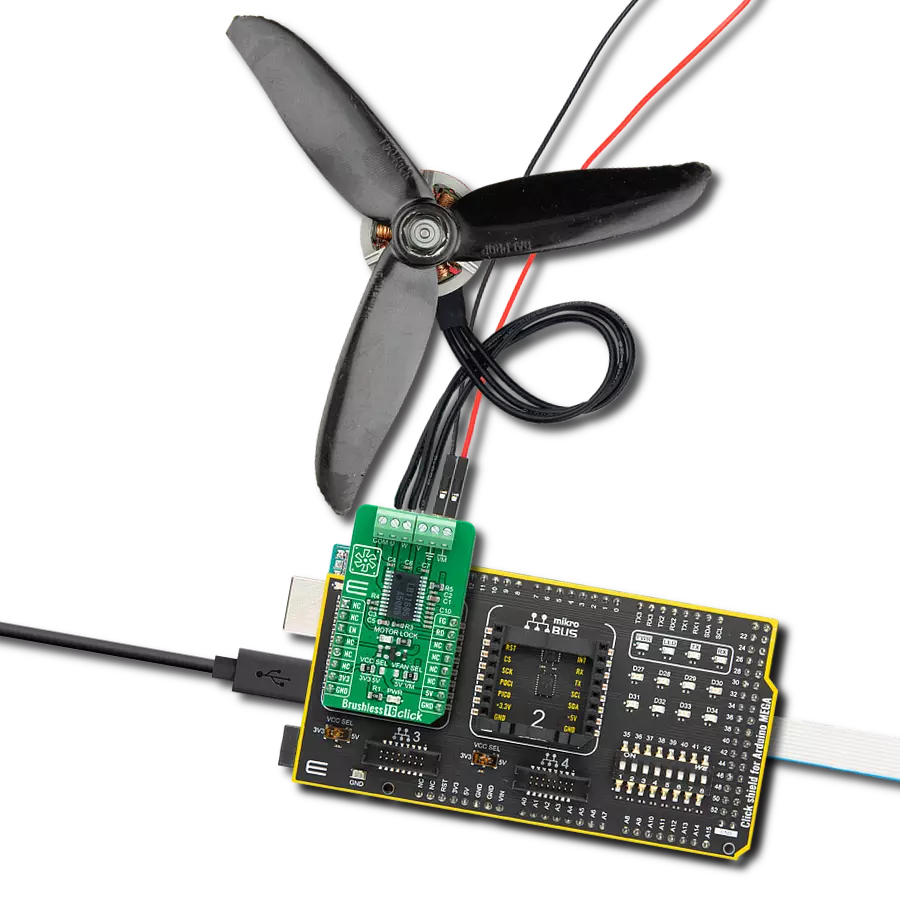
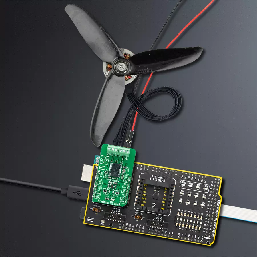
Brushless 16 Click
Dev. board
Arduino Mega 2560 Rev3
Compiler
NECTO Studio
MCU
ATmega2560
Our cutting-edge solution efficiently drives cooling fan motors, ensuring optimal airflow and temperature regulation for a refreshing and quiet environment
A
A
Hardware Overview
How does it work?
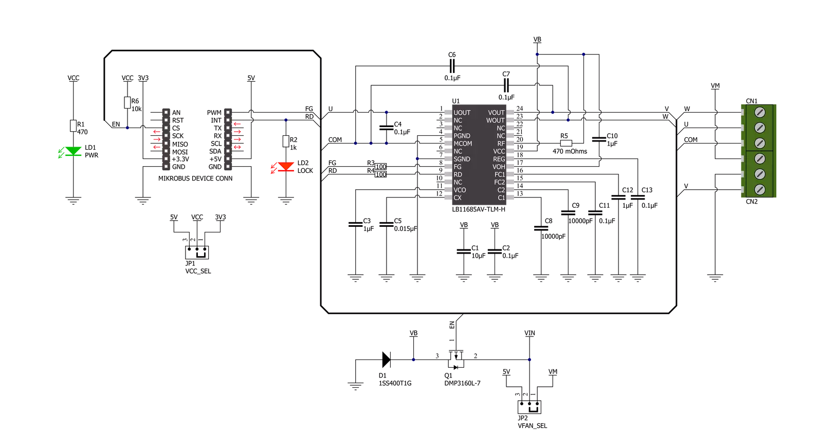
Brushless 16 Click is based on the LB11685AV, a three-phase full-wave current-linear-drive motor driver from ON Semiconductor. The LB11685AV adopts a sensorless control system without using a Hall-effect device. It features a current soft switching circuit for silent operation. It is also characterized by easy control, current limit, and various protection features. This Click board™ makes the perfect solution for delivering quiet, cool operation to home appliances and office automation equipment. Start-Up Mode is set when the LB11685AV starts its operation. After the "START" position, the LB11685AV outputs energization timing patterns for a Start-Up in each output (U/V/W) to determine the position of a motor. Based on the timing pattern, the motor starts rotation, and LB11685AV detects back-EMF, defining a motor position. As a result, the
LB11685AV outputs energization timing, which synchronizes with the motor position to the motor. That's how a motor starts rotation. When the LB11685AV switches from Start-Up Mode to Regular rotation Mode, the driving current is switched to full driving mode, which increases the rotation speed until it is stabilized. Brushless 12 Click communicates with MCU using several GPIO pins. The device can be turned on or off through a dedicated Enable (EN) pin routed on the CS pin of the mikroBUS™ socket, while the FG pin routed on the PWM pin serves as a rotation speed indicator and outputs a rectangular waveform in reverse to V motor signal made by back EMF. Besides, it is possible to detect motor lock events on the interrupt RD pin routed to the INT signal of the mikroBUS™ socket, where the indication of such a condition is performed using the red LED
indicator labeled as MOTOR LOCK. Brushless 16 Click supports an external power supply connected to the input terminal labeled as VM, next to the U, V, W, and COM terminals on which the BLDC motor needs to be connected. The absolute maximum rating of the power supply voltage is 19V which must not be exceeded, even for a moment. Do not exceed any of these ratings! This Click board™ can operate with both 3.3V and 5V logic voltage levels selected via the VCC SEL jumper. It allows both 3.3V and 5V capable MCUs to use the communication lines properly. Additionally, there is a possibility for LB11685AV power supply selection via jumper labeled as VFAN SEL to supply the LB11685AV from an external input terminal in the range from 4.5 to 19V or with a 5V from mikroBUS™ power rail.

Features overview
Development board
Arduino Mega 2560 is a robust microcontroller platform built around the ATmega 2560 chip. It has extensive capabilities and boasts 54 digital input/output pins, including 15 PWM outputs, 16 analog inputs, and 4 UARTs. With a 16MHz crystal
oscillator ensuring precise timing, it offers seamless connectivity via USB, a convenient power jack, an ICSP header, and a reset button. This all-inclusive board simplifies microcontroller projects; connect it to your computer via USB or power it up
using an AC-to-DC adapter or battery. Notably, the Mega 2560 maintains compatibility with a wide range of shields crafted for the Uno, Duemilanove, or Diecimila boards, ensuring versatility and ease of integration.

Microcontroller Overview
MCU Card / MCU

Architecture
AVR
MCU Memory (KB)
256
Silicon Vendor
Microchip
Pin count
100
RAM (Bytes)
8192
You complete me!
Accessories
Click Shield for Arduino Mega comes equipped with four mikroBUS™ sockets, with two in the form of a Shuttle connector, allowing all the Click board™ devices to be interfaced with the Arduino Mega board with no effort. Featuring an AVR 8-bit microcontroller with advanced RISC architecture, 54 digital I/O pins, and Arduino™ compatibility, the Arduino Mega board offers limitless possibilities for prototyping and creating diverse applications. This board is controlled and powered conveniently through a USB connection to program and debug the Arduino Mega board efficiently out of the box, with an additional USB cable connected to the USB B port on the board. Simplify your project development with the integrated ATmega16U2 programmer and unleash creativity using the extensive I/O options and expansion capabilities. There are eight switches, which you can use as inputs, and eight LEDs, which can be used as outputs of the MEGA2560. In addition, the shield features the MCP1501, a high-precision buffered voltage reference from Microchip. This reference is selected by default over the EXT REF jumper at the bottom of the board. You can choose an external one, as you would usually do with an Arduino Mega board. There is also a GND hook for testing purposes. Four additional LEDs are PWR, LED (standard pin D13), RX, and TX LEDs connected to UART1 (mikroBUS™ 1 socket). This Click Shield also has several switches that perform functions such as selecting the logic levels of analog signals on mikroBUS™ sockets and selecting logic voltage levels of the mikroBUS™ sockets themselves. Besides, the user is offered the possibility of using any Click board™ with the help of existing bidirectional level-shifting voltage translators, regardless of whether the Click board™ operates at a 3.3V or 5V logic voltage level. Once you connect the Arduino Mega board with Click Shield for Arduino Mega, you can access hundreds of Click boards™, working with 3.3V or 5V logic voltage levels.

2207V-2500kV BLDC Motor is an outrunner brushless DC motor with a kV rating of 2500 and an M5 shaft diameter. It is an excellent solution for fulfilling many functions initially performed by brushed DC motors or in RC drones, racing cars, and much more.

Used MCU Pins
mikroBUS™ mapper
Take a closer look
Click board™ Schematic
Step by step
Project assembly

Start by selecting your development board and Click board™. Begin with the Arduino Mega 2560 Rev3 as your development board.


Track your results in real time
Application Output
1. Application Output - In Debug mode, the 'Application Output' window enables real-time data monitoring, offering direct insight into execution results. Ensure proper data display by configuring the environment correctly using the provided tutorial.

2. UART Terminal - Use the UART Terminal to monitor data transmission via a USB to UART converter, allowing direct communication between the Click board™ and your development system. Configure the baud rate and other serial settings according to your project's requirements to ensure proper functionality. For step-by-step setup instructions, refer to the provided tutorial.

3. Plot Output - The Plot feature offers a powerful way to visualize real-time sensor data, enabling trend analysis, debugging, and comparison of multiple data points. To set it up correctly, follow the provided tutorial, which includes a step-by-step example of using the Plot feature to display Click board™ readings. To use the Plot feature in your code, use the function: plot(*insert_graph_name*, variable_name);. This is a general format, and it is up to the user to replace 'insert_graph_name' with the actual graph name and 'variable_name' with the parameter to be displayed.

Software Support
Library Description
This library contains API for Brushless 16 Click driver.
Key functions:
brushless16_set_en- This function set en pin statebrushless16_get_rd- This function get rd pin statebrushless16_get_fg- This function get fg pin state
Open Source
Code example
The complete application code and a ready-to-use project are available through the NECTO Studio Package Manager for direct installation in the NECTO Studio. The application code can also be found on the MIKROE GitHub account.
/*!
 * @file main.c
 * @brief Brushless 16 Click Example.
 *
 * # Description
 * This example showcases ability to enable and disable motor output,
 * and check the status pins.
 *
 * The demo application is composed of two sections :
 *
 * ## Application Init
 * Initializon of UART module for log and pins for motor control.
 *
 * ## Application Task
 * Checks state of information pins every ms, and stop and start motor
 * output every second.
 *
 * @author Luka Filipovic
 *
 */

#include "board.h"
#include "log.h"
#include "brushless16.h"

static brushless16_t brushless16;   /**< Brushless 16 Click driver object. */
static log_t logger;    /**< Logger object. */

void application_init ( void )
{
    log_cfg_t log_cfg;  /**< Logger config object. */
    brushless16_cfg_t brushless16_cfg;  /**< Click config object. */

    /**
     * Logger initialization.
     * Default baud rate: 115200
     * Default log level: LOG_LEVEL_DEBUG
     * @note If USB_UART_RX and USB_UART_TX
     * are defined as HAL_PIN_NC, you will
     * need to define them manually for log to work.
     * See @b LOG_MAP_USB_UART macro definition for detailed explanation.
     */
    LOG_MAP_USB_UART( log_cfg );
    log_init( &logger, &log_cfg );
    log_info( &logger, " Application Init " );

    // Click initialization.
    brushless16_cfg_setup( &brushless16_cfg );
    BRUSHLESS16_MAP_MIKROBUS( brushless16_cfg, MIKROBUS_1 );
    if ( brushless16_init( &brushless16, &brushless16_cfg ) == DIGITAL_OUT_UNSUPPORTED_PIN )
    {
        log_error( &logger, " Application Init Error. " );
        log_info( &logger, " Please, run program again... " );

        for ( ; ; );
    }
    Delay_ms ( 500 );
    log_info( &logger, " Application Task " );
}

void application_task ( void )
{
    static uint16_t timer = 5000;
    static uint8_t state = 1;

    if ( brushless16_get_rd( &brushless16 ) )
    {
        log_info( &logger, " Motor Lock" );
        Delay_ms ( 500 );
    }

    if ( brushless16_get_fg( &brushless16 ) )
    {
        log_info( &logger, " FG" );
        Delay_ms ( 500 );
    }

    if ( !( timer-- ) )
    {
        timer = 5000;

        if ( state )
        {
            log_info( &logger, " Motor stop" );
        }
        else
        {
            log_info( &logger, " Motor rotating" );
        }

        brushless16_set_en( &brushless16, state );
        state = !state;
    }

    Delay_ms ( 1 );
}

int main ( void )
{
    /* Do not remove this line or clock might not be set correctly. */
    #ifdef PREINIT_SUPPORTED
    preinit();
    #endif

    application_init( );

    for ( ; ; )
    {
        application_task( );
    }

    return 0;
}

// ------------------------------------------------------------------------ END
Additional Support
Resources
Category:Brushless


