Enter the realm of secure CAN communication with ISO1042 and ATmega2560
Drive your data forward with confidence!
Published Feb 14, 2024
Click board™
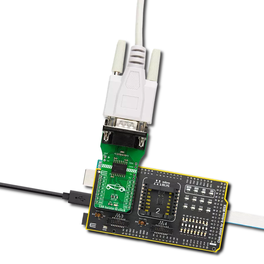
CAN Isolator 2 Click
Dev. board
Arduino Mega 2560 Rev3
Compiler
NECTO Studio
MCU
ATmega2560
This solution offers protection against ground potential differences, electrical noise, and voltage spikes, ensuring consistent and robust communication on the CAN bus.
A
A
Hardware Overview
How does it work?
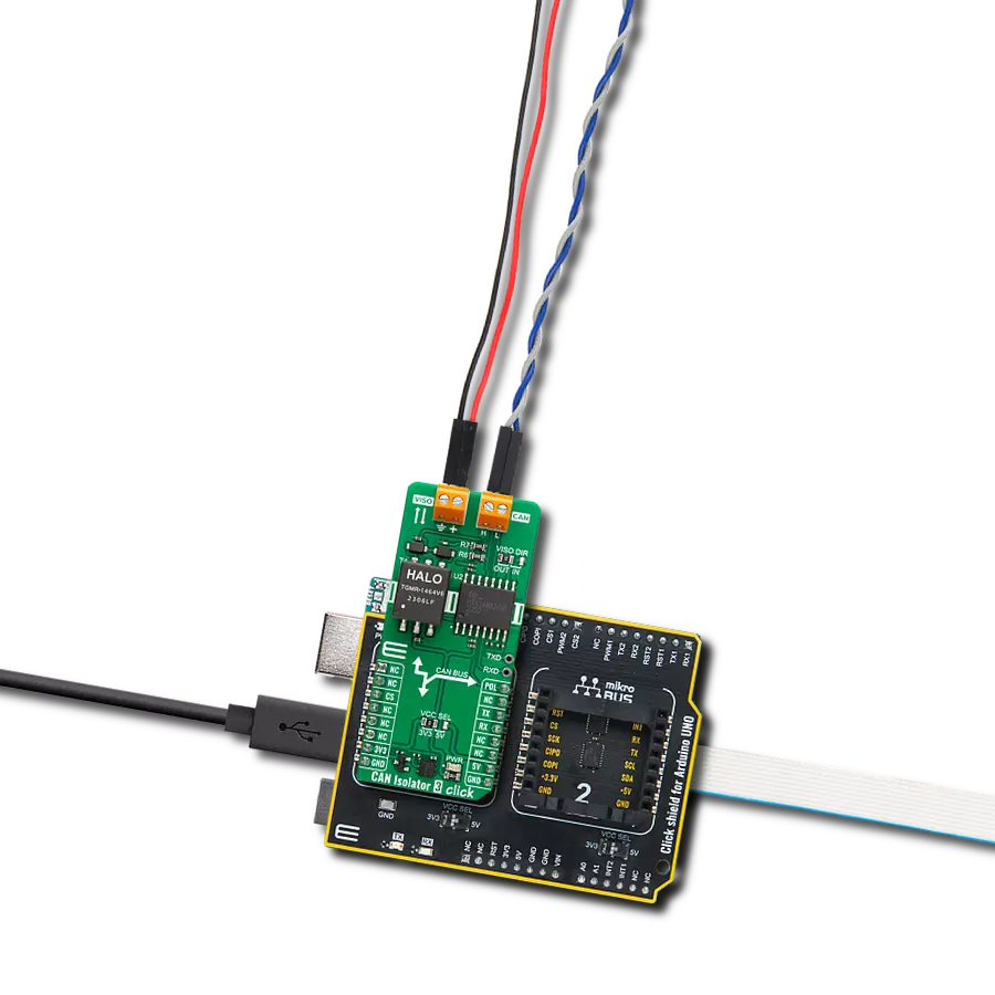
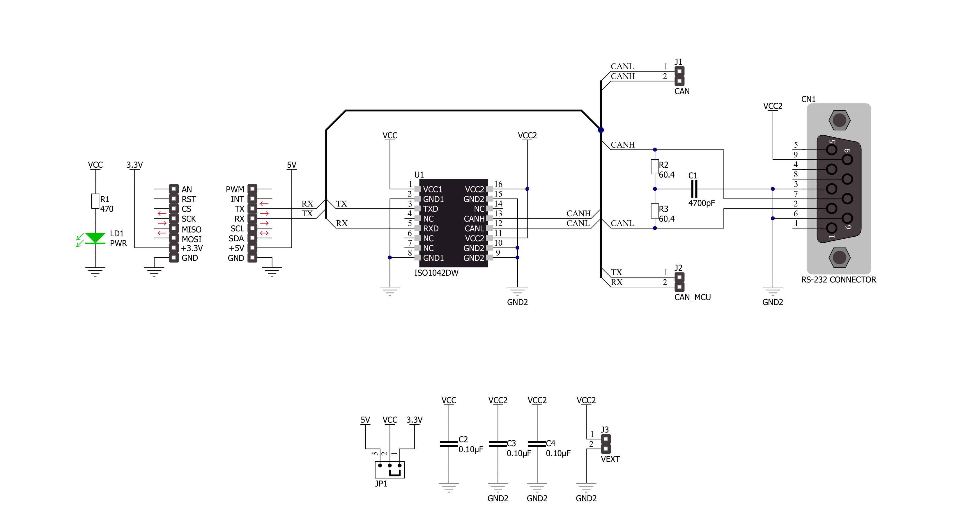
CAN Isolator 2 Click is based on the ISO1042, an isolated CAN transceiver from Texas Instruments. It has several features, such as undervoltage protection, driver Dominant Time Out (TXD DTO), HBM ESD tolerance on bus pins, and more. The transceiver has ideal passive high-impedance bus terminals when unpowered. If used in conjunction with the isolated power supplies, the CAN Isolator 2 Click can be the ideal choice for protection against high voltages and noise currents from the bus. There are two states of operation on this Click board™: dominant and recessive. In a dominant state, the bus is driven differentially by a driver. In a recessive state, the host MCU of the CAN node
uses the TXD pin to drive the bus and receives the data from the bus on the RXD pin. To connect ISO1042 on a CAN bus, this Click board™ features a standard DB 9-pin male connector. According to the ISO 11898-2 standard, a maximum bus length is 40m, and a maximum stub length is 0.3m, while with careful design, the cables could be longer. This transceiver has a high input impedance, thus allowing a large number of nodes on the CAN bus. CAN Isolator 2 Click uses a standard UART interface to communicate with the host MCU, with commonly used UART RX and TX. In addition, there are few headers to interface lines directly with jumper wires. The left side of the CAN Isolator
2 Click has a VEXT 2-pin header to connect the external power supply. Along with the VEXT, on the opposite side, there are CANH and CANL pins to interface the CAN bus in the same manner. Under the CAN header, there is also one TX and RX header, which allows this Click board™ to be used independently of the host MCU. This Click board™ can operate with either 3.3V or 5V logic voltage levels selected via the VCC SEL jumper. This way, both 3.3V and 5V capable MCUs can use the communication lines properly. Also, this Click board™ comes equipped with a library containing easy-to-use functions and an example code that can be used for further development.

Features overview
Development board
Arduino Mega 2560 is a robust microcontroller platform built around the ATmega 2560 chip. It has extensive capabilities and boasts 54 digital input/output pins, including 15 PWM outputs, 16 analog inputs, and 4 UARTs. With a 16MHz crystal
oscillator ensuring precise timing, it offers seamless connectivity via USB, a convenient power jack, an ICSP header, and a reset button. This all-inclusive board simplifies microcontroller projects; connect it to your computer via USB or power it up
using an AC-to-DC adapter or battery. Notably, the Mega 2560 maintains compatibility with a wide range of shields crafted for the Uno, Duemilanove, or Diecimila boards, ensuring versatility and ease of integration.

Microcontroller Overview
MCU Card / MCU

Architecture
AVR
MCU Memory (KB)
256
Silicon Vendor
Microchip
Pin count
100
RAM (Bytes)
8192
You complete me!
Accessories
Click Shield for Arduino Mega comes equipped with four mikroBUS™ sockets, with two in the form of a Shuttle connector, allowing all the Click board™ devices to be interfaced with the Arduino Mega board with no effort. Featuring an AVR 8-bit microcontroller with advanced RISC architecture, 54 digital I/O pins, and Arduino™ compatibility, the Arduino Mega board offers limitless possibilities for prototyping and creating diverse applications. This board is controlled and powered conveniently through a USB connection to program and debug the Arduino Mega board efficiently out of the box, with an additional USB cable connected to the USB B port on the board. Simplify your project development with the integrated ATmega16U2 programmer and unleash creativity using the extensive I/O options and expansion capabilities. There are eight switches, which you can use as inputs, and eight LEDs, which can be used as outputs of the MEGA2560. In addition, the shield features the MCP1501, a high-precision buffered voltage reference from Microchip. This reference is selected by default over the EXT REF jumper at the bottom of the board. You can choose an external one, as you would usually do with an Arduino Mega board. There is also a GND hook for testing purposes. Four additional LEDs are PWR, LED (standard pin D13), RX, and TX LEDs connected to UART1 (mikroBUS™ 1 socket). This Click Shield also has several switches that perform functions such as selecting the logic levels of analog signals on mikroBUS™ sockets and selecting logic voltage levels of the mikroBUS™ sockets themselves. Besides, the user is offered the possibility of using any Click board™ with the help of existing bidirectional level-shifting voltage translators, regardless of whether the Click board™ operates at a 3.3V or 5V logic voltage level. Once you connect the Arduino Mega board with Click Shield for Arduino Mega, you can access hundreds of Click boards™, working with 3.3V or 5V logic voltage levels.

DB9 Cable Female-to-Female (2m) cable is essential for establishing dependable serial data connections between devices. With its DB9 female connectors on both ends, this cable enables a seamless link between various equipment, such as computers, routers, switches, and other serial devices. Measuring 2 meters in length, it offers flexibility in arranging your setup without compromising data transmission quality. Crafted with precision, this cable ensures consistent and reliable data exchange, making it suitable for industrial applications, office environments, and home setups. Whether configuring networking equipment, accessing console ports, or utilizing serial peripherals, this cable's durable construction and robust connectors guarantee a stable connection. Simplify your data communication needs with the 2m DB9 female-to-female cable, an efficient solution designed to meet your serial connectivity requirements easily and efficiently.

Used MCU Pins
mikroBUS™ mapper
Take a closer look
Click board™ Schematic
Step by step
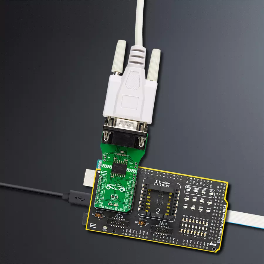
Project assembly

Start by selecting your development board and Click board™. Begin with the Arduino Mega 2560 Rev3 as your development board.


Track your results in real time
Application Output
1. Application Output - In Debug mode, the 'Application Output' window enables real-time data monitoring, offering direct insight into execution results. Ensure proper data display by configuring the environment correctly using the provided tutorial.

2. UART Terminal - Use the UART Terminal to monitor data transmission via a USB to UART converter, allowing direct communication between the Click board™ and your development system. Configure the baud rate and other serial settings according to your project's requirements to ensure proper functionality. For step-by-step setup instructions, refer to the provided tutorial.

3. Plot Output - The Plot feature offers a powerful way to visualize real-time sensor data, enabling trend analysis, debugging, and comparison of multiple data points. To set it up correctly, follow the provided tutorial, which includes a step-by-step example of using the Plot feature to display Click board™ readings. To use the Plot feature in your code, use the function: plot(*insert_graph_name*, variable_name);. This is a general format, and it is up to the user to replace 'insert_graph_name' with the actual graph name and 'variable_name' with the parameter to be displayed.

Software Support
Library Description
This library contains API for CAN Isolator 2 Click driver.
Key functions:
canisolator2_generic_write- CAN Isolator 2 data writing function.canisolator2_generic_read-CAN Isolator 2 data reading function.canisolator2_send_data- CAN Isolator 2 send data function.
Open Source
Code example
The complete application code and a ready-to-use project are available through the NECTO Studio Package Manager for direct installation in the NECTO Studio. The application code can also be found on the MIKROE GitHub account.
/*!
 * @file main.c
 * @brief CAN Isolator 2 Click Example.
 *
 * # Description
 * This example reads and processes data from CAN Isolator 2 Clicks.
 *
 * The demo application is composed of two sections :
 *
 * ## Application Init
 * Initializes driver and wake-up module.
 *
 * ## Application Task
 * Transmitter/Receiver task depends on uncommented code.
 * Receiver logging each received byte to the UART for data logging,
 * while transmitted send messages every 2 seconds.
 *
 * ## Additional Function
 * - static void canisolator2_clear_app_buf ( void )
 * - static err_t canisolator2_process ( void )
 *
 * @author Nenad Filipovic
 *
 */

#include "board.h"
#include "log.h"
#include "canisolator2.h"

#define PROCESS_BUFFER_SIZE 200

// #define TRANSMIT
#define RECIEVER

static canisolator2_t canisolator2;
static log_t logger;

static char app_buf[ PROCESS_BUFFER_SIZE ] = { 0 };
static int32_t app_buf_len = 0;
static int32_t app_buf_cnt = 0;

unsigned char demo_message[ 9 ] = { 'M', 'i', 'k', 'r', 'o', 'E', 13, 10, 0 };

/**
 * @brief CAN Isolator 2 clearing application buffer.
 * @details This function clears memory of application buffer and reset it's length and counter.
 * @note None.
 */
static void canisolator2_clear_app_buf ( void );

/**
 * @brief CAN Isolator 2 data reading function.
 * @details This function reads data from device and concatenates data to application buffer.
 *
 * @return @li @c  0 - Read some data.
 *         @li @c -1 - Nothing is read.
 *         @li @c -2 - Application buffer overflow.
 *
 * See #err_t definition for detailed explanation.
 * @note None.
 */
static err_t canisolator2_process ( void );

void application_init ( void ) {
    log_cfg_t log_cfg;                    /**< Logger config object. */
    canisolator2_cfg_t canisolator2_cfg;  /**< Click config object. */

    /**
     * Logger initialization.
     * Default baud rate: 115200
     * Default log level: LOG_LEVEL_DEBUG
     * @note If USB_UART_RX and USB_UART_TX
     * are defined as HAL_PIN_NC, you will
     * need to define them manually for log to work.
     * See @b LOG_MAP_USB_UART macro definition for detailed explanation.
     */
    LOG_MAP_USB_UART( log_cfg );
    log_init( &logger, &log_cfg );
    log_info( &logger, " Application Init " );

    // Click initialization.

    canisolator2_cfg_setup( &canisolator2_cfg );
    CANISOLATOR2_MAP_MIKROBUS( canisolator2_cfg, MIKROBUS_1 );
    err_t init_flag  = canisolator2_init( &canisolator2, &canisolator2_cfg );
    if ( init_flag == UART_ERROR ) {
        log_error( &logger, " Application Init Error. " );
        log_info( &logger, " Please, run program again... " );

        for ( ; ; );
    }

    app_buf_len = 0;
    app_buf_cnt = 0;
    log_info( &logger, " Application Task " );
    Delay_ms ( 100 );

    #ifdef TRANSMIT

        log_printf( &logger, "    Send data:    \r\n" );
        log_printf( &logger, "      MikroE      \r\n" );
        log_printf( &logger, "------------------\r\n" );
        log_printf( &logger, "  Transmit data   \r\n" );
        Delay_ms ( 1000 );

    #endif

    #ifdef RECIEVER

        log_printf( &logger, "   Receive data  \r\n" );
        Delay_ms ( 1000 );
        Delay_ms ( 1000 );

    #endif

    log_printf( &logger, "------------------\r\n" );
}

void application_task ( void ) {
   #ifdef TRANSMIT

        canisolator2_send_data( &canisolator2, demo_message );
        log_printf( &logger, "\t%s", demo_message );
        Delay_ms ( 1000 );
        Delay_ms ( 1000 );
        log_printf( &logger, "------------------\r\n" );

    #endif

    #ifdef RECIEVER

        canisolator2_process( );

        if ( app_buf_len > 0 ) {
            log_printf( &logger, "%s", app_buf );
            canisolator2_clear_app_buf(  );
        }

    #endif
}

int main ( void )
{
    /* Do not remove this line or clock might not be set correctly. */
    #ifdef PREINIT_SUPPORTED
    preinit();
    #endif

    application_init( );

    for ( ; ; )
    {
        application_task( );
    }

    return 0;
}

static void canisolator2_clear_app_buf ( void ) {
    memset( app_buf, 0, app_buf_len );
    app_buf_len = 0;
    app_buf_cnt = 0;
}

static err_t canisolator2_process ( void ) {
    int32_t rx_size;
    char rx_buff[ PROCESS_BUFFER_SIZE ] = { 0 };

    rx_size = canisolator2_generic_read( &canisolator2, rx_buff, PROCESS_BUFFER_SIZE );

    if ( rx_size > 0 ) {
        int32_t buf_cnt = 0;

        if ( app_buf_len + rx_size >= PROCESS_BUFFER_SIZE ) {
           canisolator2_clear_app_buf(  );
            return CANISOLATOR2_ERROR;
        } else {
            buf_cnt = app_buf_len;
            app_buf_len += rx_size;
        }

        for ( int32_t rx_cnt = 0; rx_cnt < rx_size; rx_cnt++ ) {
            if ( rx_buff[ rx_cnt ] != 0 ) {
                app_buf[ ( buf_cnt + rx_cnt ) ] = rx_buff[ rx_cnt ];
            } else {
                app_buf_len--;
                buf_cnt--;
            }

        }
        return CANISOLATOR2_OK;
    }
    return CANISOLATOR2_ERROR;
}

// ------------------------------------------------------------------------ END
Additional Support
Resources
Category:CAN