Keep CAN communication secure with MAX14882 and ATmega2560
Enhance the reliability and performance of the CAN bus in challenging environments
Published Feb 14, 2024
Click board™
CAN Isolator 3 Click
Dev. board
Arduino Mega 2560 Rev3
Compiler
NECTO Studio
MCU
ATmega2560
Provide protection from overvoltage transients between the CAN bus cable network and the systems connected to it
A
A
Hardware Overview
How does it work?
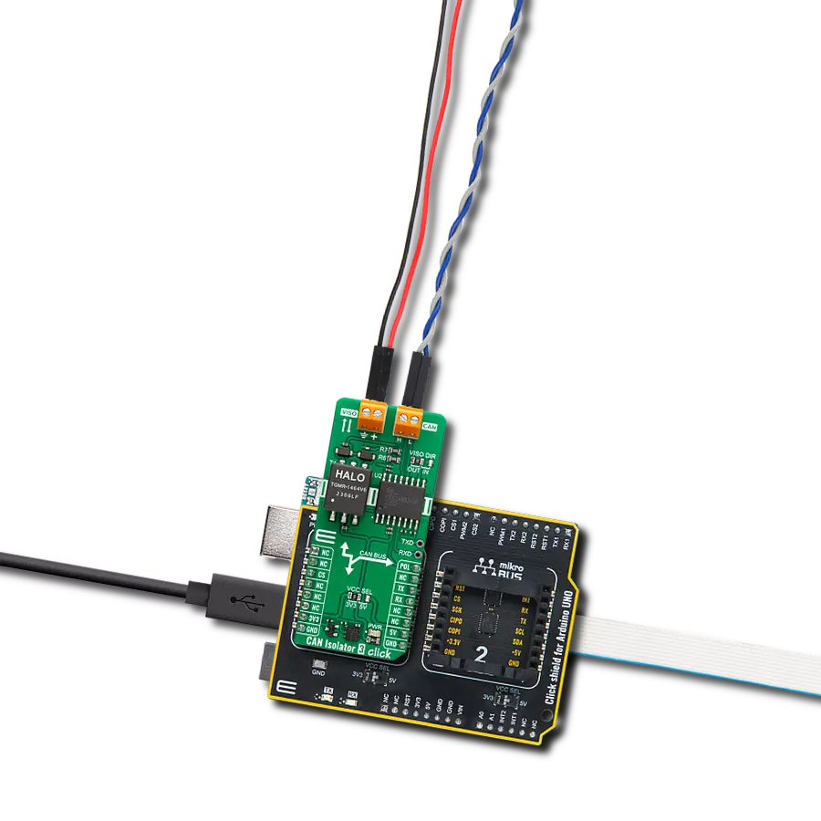
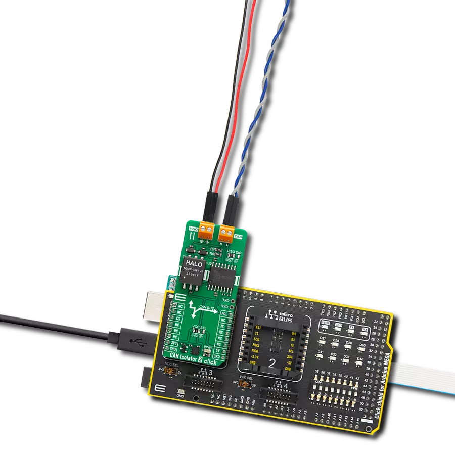
CAN Isolator 3 Click is based on MAX14882, an isolated CAN transceiver with an integrated transformer driver from Analog Devices. Its features include a wide supply voltage range for the CAN controller interface (3V – 5V), field bus polarity control (POL), an integrated transformer driver for power transfer to the bus side, and an integrated LDO for powering the CAN bus side. The CAN bus controller exceeds the ISO 11898 specifications requirement of -2V to +7V with ±25V receiver input common-mode range. Additionally, the CANH and CANL IOs are fault tolerant up to ±54V and protected from electronic discharge (ESD) up to ±15KV to GNDB on the bus side. CAN
Isolator 3 Click is equipped with CAN and VISO terminals, where the VISO terminal can be a bus-side power input or an LDO power output terminal. If used as an LDO power output, you can count up to 5V of VDDB voltage on this terminal. You can select the input/output direction over the VISO DIR jumper, where the isolated voltage as output (OUT) is set by default. In this default configuration, the reinforced insulation module can supply to the VISO terminal 3.3V or 5V, depending on the selected voltage on the VCC SEL jumper, as the 3.3V is selected by default. CAN Isolator 3 Click uses a standard UART serial interface to communicate with the host MCU over
commonly used UART RX and TX pins. The RX and TX are also available on a separate header for testing purposes. The polarity of the CAN controller can be set over the POL pin with a LOW logic state for normal CANH and CANL operation and HIGH to swap the functions of the CANH and CANL. This Click board™ can operate with either 3.3V or 5V logic voltage levels selected via the VCC SEL jumper. This way, both 3.3V and 5V capable MCUs can use the communication lines properly. Also, this Click board™ comes equipped with a library containing easy-to-use functions and an example code that can be used as a reference for further development.

Features overview
Development board
Arduino Mega 2560 is a robust microcontroller platform built around the ATmega 2560 chip. It has extensive capabilities and boasts 54 digital input/output pins, including 15 PWM outputs, 16 analog inputs, and 4 UARTs. With a 16MHz crystal
oscillator ensuring precise timing, it offers seamless connectivity via USB, a convenient power jack, an ICSP header, and a reset button. This all-inclusive board simplifies microcontroller projects; connect it to your computer via USB or power it up
using an AC-to-DC adapter or battery. Notably, the Mega 2560 maintains compatibility with a wide range of shields crafted for the Uno, Duemilanove, or Diecimila boards, ensuring versatility and ease of integration.

Microcontroller Overview
MCU Card / MCU

Architecture
AVR
MCU Memory (KB)
256
Silicon Vendor
Microchip
Pin count
100
RAM (Bytes)
8192
You complete me!
Accessories
Click Shield for Arduino Mega comes equipped with four mikroBUS™ sockets, with two in the form of a Shuttle connector, allowing all the Click board™ devices to be interfaced with the Arduino Mega board with no effort. Featuring an AVR 8-bit microcontroller with advanced RISC architecture, 54 digital I/O pins, and Arduino™ compatibility, the Arduino Mega board offers limitless possibilities for prototyping and creating diverse applications. This board is controlled and powered conveniently through a USB connection to program and debug the Arduino Mega board efficiently out of the box, with an additional USB cable connected to the USB B port on the board. Simplify your project development with the integrated ATmega16U2 programmer and unleash creativity using the extensive I/O options and expansion capabilities. There are eight switches, which you can use as inputs, and eight LEDs, which can be used as outputs of the MEGA2560. In addition, the shield features the MCP1501, a high-precision buffered voltage reference from Microchip. This reference is selected by default over the EXT REF jumper at the bottom of the board. You can choose an external one, as you would usually do with an Arduino Mega board. There is also a GND hook for testing purposes. Four additional LEDs are PWR, LED (standard pin D13), RX, and TX LEDs connected to UART1 (mikroBUS™ 1 socket). This Click Shield also has several switches that perform functions such as selecting the logic levels of analog signals on mikroBUS™ sockets and selecting logic voltage levels of the mikroBUS™ sockets themselves. Besides, the user is offered the possibility of using any Click board™ with the help of existing bidirectional level-shifting voltage translators, regardless of whether the Click board™ operates at a 3.3V or 5V logic voltage level. Once you connect the Arduino Mega board with Click Shield for Arduino Mega, you can access hundreds of Click boards™, working with 3.3V or 5V logic voltage levels.

Used MCU Pins
mikroBUS™ mapper
Take a closer look
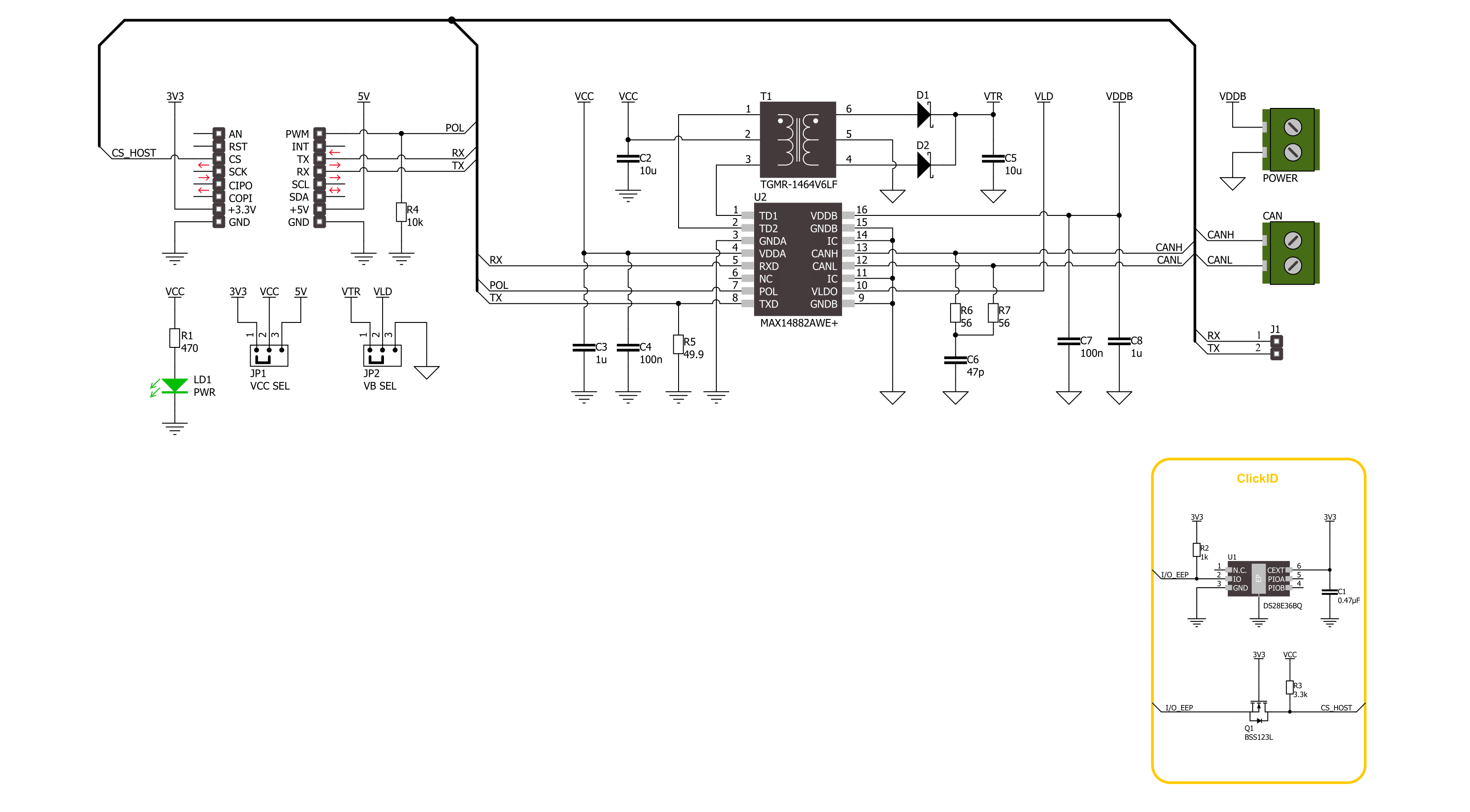
Click board™ Schematic
Step by step
Project assembly

Start by selecting your development board and Click board™. Begin with the Arduino Mega 2560 Rev3 as your development board.


Track your results in real time
Application Output
1. Application Output - In Debug mode, the 'Application Output' window enables real-time data monitoring, offering direct insight into execution results. Ensure proper data display by configuring the environment correctly using the provided tutorial.

2. UART Terminal - Use the UART Terminal to monitor data transmission via a USB to UART converter, allowing direct communication between the Click board™ and your development system. Configure the baud rate and other serial settings according to your project's requirements to ensure proper functionality. For step-by-step setup instructions, refer to the provided tutorial.

3. Plot Output - The Plot feature offers a powerful way to visualize real-time sensor data, enabling trend analysis, debugging, and comparison of multiple data points. To set it up correctly, follow the provided tutorial, which includes a step-by-step example of using the Plot feature to display Click board™ readings. To use the Plot feature in your code, use the function: plot(*insert_graph_name*, variable_name);. This is a general format, and it is up to the user to replace 'insert_graph_name' with the actual graph name and 'variable_name' with the parameter to be displayed.

Software Support
Library Description
This library contains API for CAN Isolator 3 Click driver.
Key functions:
canisolator3_generic_write- CAN Isolator 3 data writing function.canisolator3_generic_read- CAN Isolator 3 data reading function.canisolator3_set_pol_pin- CAN Isolator 3 set polarity function.
Open Source
Code example
The complete application code and a ready-to-use project are available through the NECTO Studio Package Manager for direct installation in the NECTO Studio. The application code can also be found on the MIKROE GitHub account.
/*!
 * @file main.c
 * @brief CAN Isolator 3 Click Example.
 *
 * # Description
 * This example writes and reads and processes data from CAN Isolator 3 Click.
 * The library also includes a function for selection of the output polarity.
 *
 * The demo application is composed of two sections :
 *
 * ## Application Init
 * Initializes the driver and performs the Click default configuration.
 *
 * ## Application Task
 * This example contains Transmitter/Receiver task depending on uncommented code.
 * Receiver logs each received byte to the UART for data logging,
 * while the transmitter sends messages every 2 seconds.
 *
 * ## Additional Function
 * - static err_t canisolator3_process ( canisolator3_t *ctx )
 *
 * @author Stefan Ilic
 *
 */

#include "board.h"
#include "log.h"
#include "canisolator3.h"

#define PROCESS_BUFFER_SIZE 200
#define TX_MESSAGE "CAN Isolator 3 Click \r\n"

// Comment out the line below in order to switch the application mode to receiver.
#define DEMO_APP_TRANSMITTER

static canisolator3_t canisolator3;
static log_t logger;

static uint8_t app_buf[ PROCESS_BUFFER_SIZE ] = { 0 };
static int32_t app_buf_len = 0;

/**
 * @brief CAN Isolator 3 data reading function.
 * @details This function reads data from device and concatenates data to application buffer.
 * @param[in] ctx : Click context object.
 * See #canisolator3_t object definition for detailed explanation.
 * @return @li @c  0 - Read some data.
 *         @li @c -1 - Nothing is read.
 * See #err_t definition for detailed explanation.
 * @note None.
 */
static err_t canisolator3_process ( canisolator3_t *ctx );

void application_init ( void )
{
    log_cfg_t log_cfg;  /**< Logger config object. */
    canisolator3_cfg_t canisolator3_cfg;  /**< Click config object. */

    /**
     * Logger initialization.
     * Default baud rate: 115200
     * Default log level: LOG_LEVEL_DEBUG
     * @note If USB_UART_RX and USB_UART_TX
     * are defined as HAL_PIN_NC, you will
     * need to define them manually for log to work.
     * See @b LOG_MAP_USB_UART macro definition for detailed explanation.
     */
    LOG_MAP_USB_UART( log_cfg );
    log_init( &logger, &log_cfg );
    log_info( &logger, " Application Init " );

    // Click initialization.
    canisolator3_cfg_setup( &canisolator3_cfg );
    CANISOLATOR3_MAP_MIKROBUS( canisolator3_cfg, MIKROBUS_1 );
    if ( UART_ERROR == canisolator3_init( &canisolator3, &canisolator3_cfg ) )
    {
        log_error( &logger, " Communication init." );
        for ( ; ; );
    }

    canisolator3_default_cfg ( &canisolator3 );

#ifdef DEMO_APP_TRANSMITTER
    log_info( &logger, "---- Transmitter mode ----" );
#else
    log_info( &logger, "---- Receiver mode ----" );
#endif

    log_info( &logger, " Application Task " );
}

void application_task ( void )
{
#ifdef DEMO_APP_TRANSMITTER
    canisolator3_generic_write( &canisolator3, TX_MESSAGE, strlen( TX_MESSAGE ) );
    log_info( &logger, "---- Data sent ----" );
    Delay_ms ( 1000 );
    Delay_ms ( 1000 );
#else
    canisolator3_process( &canisolator3 );
#endif
}

int main ( void )
{
    /* Do not remove this line or clock might not be set correctly. */
    #ifdef PREINIT_SUPPORTED
    preinit();
    #endif

    application_init( );

    for ( ; ; )
    {
        application_task( );
    }

    return 0;
}

static err_t canisolator3_process ( canisolator3_t *ctx )
{
    uint32_t rx_size;
    char rx_buf[ PROCESS_BUFFER_SIZE ] = { 0 };
    rx_size = canisolator3_generic_read( &canisolator3, rx_buf, PROCESS_BUFFER_SIZE );
    if ( rx_size > 0 )
    {
        log_printf( &logger, "%s", rx_buf );
        return CANISOLATOR3_OK;
    }
    return CANISOLATOR3_ERROR;
}

// ------------------------------------------------------------------------ END
Additional Support
Resources
Category:CAN