Unleash the potential of your DC brushed motor with TC78H653FTG and ATmega2560
Smooth moves, sharp turns
Published Feb 14, 2024
Click board™
DC Motor 19 Click
Dev. board
Arduino Mega 2560 Rev3
Compiler
NECTO Studio
MCU
ATmega2560
Ensure smooth and reliable operation for robotics and automation systems
A
A
Hardware Overview
How does it work?
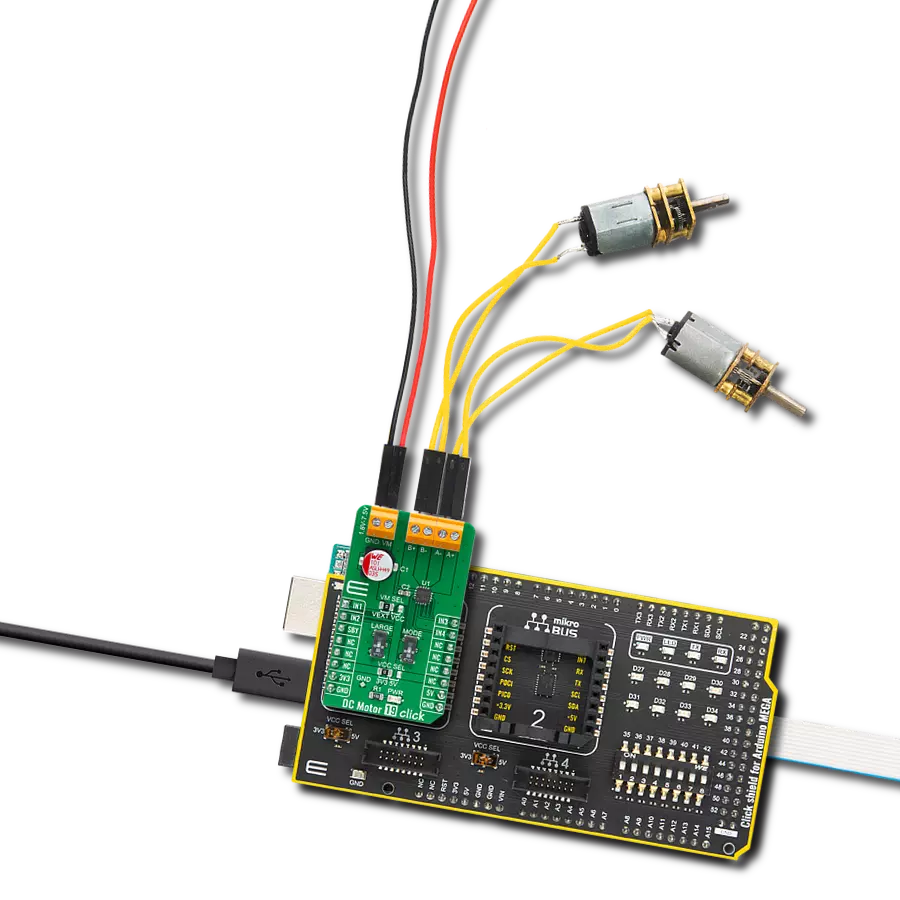
DC Motor 19 Click is based on the TC78H653FTG, a dual H-bridge driver for one or two DC brushed motors or one stepping motor from Toshiba Semiconductor. The integrated MOSFETs, configured with an H-Bridge circuit inside the TC78H653FTG, use DMOS elements with low-on resistance (0.11Ω typical with 5V power supply and activated Large mode). It has a wide operating voltage range with an output current capacity of 4A (DC) and control functions, including motor-related functions (Forward, Reverse, Brake, Stop), current control, and built-in detection circuits for overcurrent, overheat, and low/high voltage. As mentioned in the product description, DC Motor 19 Click communicates with MCU using several GPIO pins. Also, this Click board™ has a Standby pin labeled as SBY routed to the CS pin of the mikroBUS™ socket used to switch to Standby
mode by toggling the pin. When the SBY pin is low, TC78H653FTG stops supplying the power to the logic circuit, with the Standby current significantly reduced because all circuits in the IC are configured with CMOS/DMOS elements, and the current consumption in this mode is 0μA typical. To turn ON the internal MOSFETs of the TC78H653FTG, they need to be switched by the logic level, which is input to the control input pins: IN1, IN2, IN3, and IN4 pins routed to the RST, AN, PWM, and INT pins of the mikroBUS™ socket. Thereby, the Forward/Reverse/Brake/Stop rotation direction mode can be selected according to the state of its input control signals, while the motor operation and current mode can be chosen through onboard switches labeled as MODE and LARGE alongside control signals. With active LARGE mode, IN1 and IN2 pins control this
mode while motor control pins A+ and A- are connected as OUT+ and pins B- and B+ pins are connected as OUT- pins. More information on the Motor Mode Selection can be found in the attached datasheet. The DC Motor 19 supports an external power supply for the TC78H653FTG, which can be connected to the input terminal labeled as VM and should be within the range of 1.8V to 7.5V, while the DC motor coils can be connected to the terminals labeled as B+, B-, A-, and A+. This Click board™ can operate with either 3.3V or 5V logic voltage levels selected via the VCC SEL jumper. This way, both 3.3V and 5V capable MCUs can use the communication lines properly. The Click board™ comes equipped with a library containing easy-to-use functions and an example code that can be used, as a reference, for further development.

Features overview
Development board
Arduino Mega 2560 is a robust microcontroller platform built around the ATmega 2560 chip. It has extensive capabilities and boasts 54 digital input/output pins, including 15 PWM outputs, 16 analog inputs, and 4 UARTs. With a 16MHz crystal
oscillator ensuring precise timing, it offers seamless connectivity via USB, a convenient power jack, an ICSP header, and a reset button. This all-inclusive board simplifies microcontroller projects; connect it to your computer via USB or power it up
using an AC-to-DC adapter or battery. Notably, the Mega 2560 maintains compatibility with a wide range of shields crafted for the Uno, Duemilanove, or Diecimila boards, ensuring versatility and ease of integration.

Microcontroller Overview
MCU Card / MCU

Architecture
AVR
MCU Memory (KB)
256
Silicon Vendor
Microchip
Pin count
100
RAM (Bytes)
8192
You complete me!
Accessories
Click Shield for Arduino Mega comes equipped with four mikroBUS™ sockets, with two in the form of a Shuttle connector, allowing all the Click board™ devices to be interfaced with the Arduino Mega board with no effort. Featuring an AVR 8-bit microcontroller with advanced RISC architecture, 54 digital I/O pins, and Arduino™ compatibility, the Arduino Mega board offers limitless possibilities for prototyping and creating diverse applications. This board is controlled and powered conveniently through a USB connection to program and debug the Arduino Mega board efficiently out of the box, with an additional USB cable connected to the USB B port on the board. Simplify your project development with the integrated ATmega16U2 programmer and unleash creativity using the extensive I/O options and expansion capabilities. There are eight switches, which you can use as inputs, and eight LEDs, which can be used as outputs of the MEGA2560. In addition, the shield features the MCP1501, a high-precision buffered voltage reference from Microchip. This reference is selected by default over the EXT REF jumper at the bottom of the board. You can choose an external one, as you would usually do with an Arduino Mega board. There is also a GND hook for testing purposes. Four additional LEDs are PWR, LED (standard pin D13), RX, and TX LEDs connected to UART1 (mikroBUS™ 1 socket). This Click Shield also has several switches that perform functions such as selecting the logic levels of analog signals on mikroBUS™ sockets and selecting logic voltage levels of the mikroBUS™ sockets themselves. Besides, the user is offered the possibility of using any Click board™ with the help of existing bidirectional level-shifting voltage translators, regardless of whether the Click board™ operates at a 3.3V or 5V logic voltage level. Once you connect the Arduino Mega board with Click Shield for Arduino Mega, you can access hundreds of Click boards™, working with 3.3V or 5V logic voltage levels.

DC Gear Motor - 430RPM (3-6V) represents an all-in-one combination of a motor and gearbox, where the addition of gear leads to a reduction of motor speed while increasing the torque output. This gear motor has a spur gearbox, making it a highly reliable solution for applications with lower torque and speed requirements. The most critical parameters for gear motors are speed, torque, and efficiency, which are, in this case, 520RPM with no load and 430RPM at maximum efficiency, alongside a current of 60mA and a torque of 50g.cm. Rated for a 3-6V operational voltage range and clockwise/counterclockwise rotation direction, this motor represents an excellent solution for many functions initially performed by brushed DC motors in robotics, medical equipment, electric door locks, and much more.

Used MCU Pins
mikroBUS™ mapper
Take a closer look
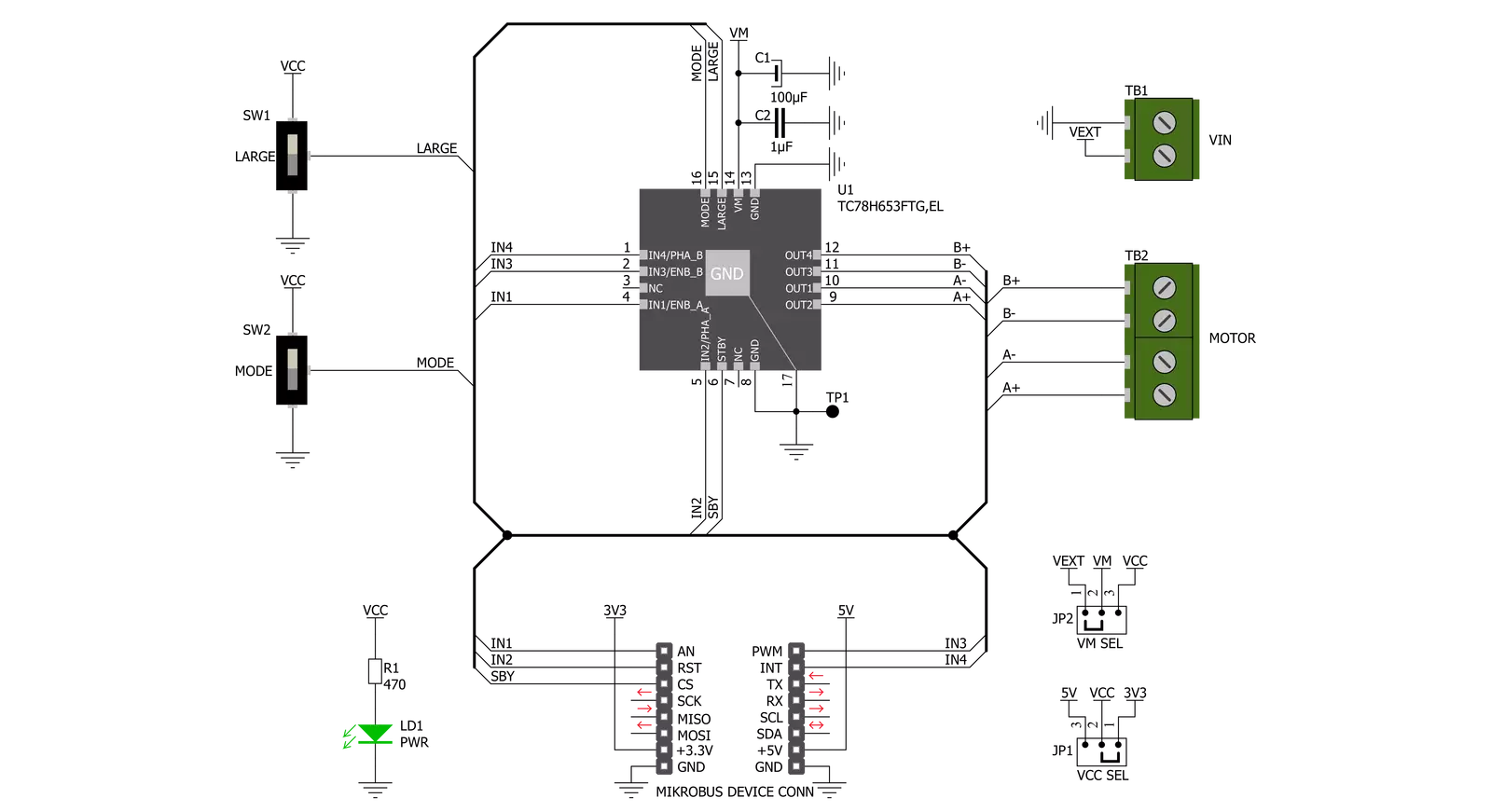
Click board™ Schematic
Step by step
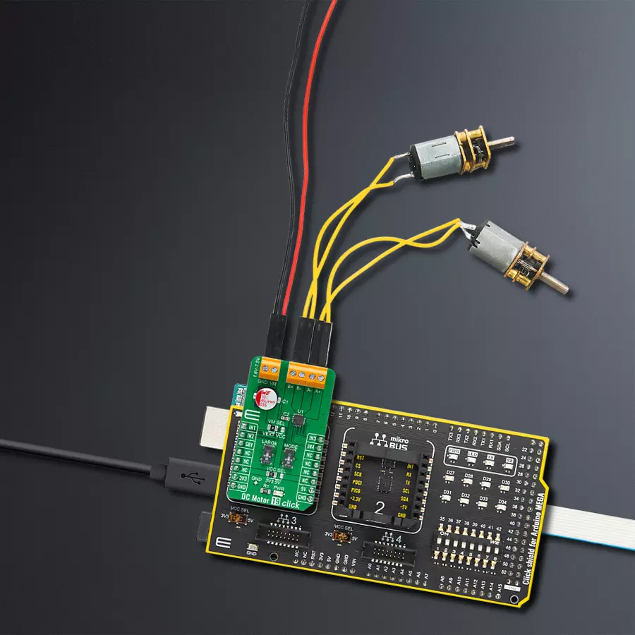
Project assembly

Start by selecting your development board and Click board™. Begin with the Arduino Mega 2560 Rev3 as your development board.


Track your results in real time
Application Output
1. Application Output - In Debug mode, the 'Application Output' window enables real-time data monitoring, offering direct insight into execution results. Ensure proper data display by configuring the environment correctly using the provided tutorial.

2. UART Terminal - Use the UART Terminal to monitor data transmission via a USB to UART converter, allowing direct communication between the Click board™ and your development system. Configure the baud rate and other serial settings according to your project's requirements to ensure proper functionality. For step-by-step setup instructions, refer to the provided tutorial.

3. Plot Output - The Plot feature offers a powerful way to visualize real-time sensor data, enabling trend analysis, debugging, and comparison of multiple data points. To set it up correctly, follow the provided tutorial, which includes a step-by-step example of using the Plot feature to display Click board™ readings. To use the Plot feature in your code, use the function: plot(*insert_graph_name*, variable_name);. This is a general format, and it is up to the user to replace 'insert_graph_name' with the actual graph name and 'variable_name' with the parameter to be displayed.

Software Support
Library Description
This library contains API for DC Motor 19 Click driver.
Key functions:
dcmotor19_drive_motor- This function drives the motor for a certian time specified by time_ms at the desired speed. The motor channel and mode must be previously selected using the dcmotor19_set_channel_mode functiondcmotor19_set_channel_mode- This function sets the active channel and mode which will be used by the dcmotor19_drive_motor functiondcmotor19_disable_standby_mode- This function disables the standby mode
Open Source
Code example
The complete application code and a ready-to-use project are available through the NECTO Studio Package Manager for direct installation in the NECTO Studio. The application code can also be found on the MIKROE GitHub account.
/*!
 * @file main.c
 * @brief DC Motor 19 Click Example.
 *
 * # Description
 * This example demonstrates the use of DC Motor 19 Click board by driving the motors
 * in both direction in the span of 14 seconds.
 *
 * The demo application is composed of two sections :
 *
 * ## Application Init
 * Initializes the driver and enables the Click by disabling the standby mode.
 *
 * ## Application Task
 * Drives the motors in the forward direction for 5 seconds, then pulls brake for 2 seconds,
 * and after that drives them in the reverse direction for 5 seconds, and finally,
 * stops driving for 2 seconds which basically disconnects the motors.
 * Each step will be logged on the USB UART where you can track the program flow.
 *
 * @author Stefan Filipovic
 *
 */

#include "board.h"
#include "log.h"
#include "dcmotor19.h"

static dcmotor19_t dcmotor19;   /**< DC Motor 19 Click driver object. */
static log_t logger;            /**< Logger object. */

void application_init ( void )
{
    log_cfg_t log_cfg;              /**< Logger config object. */
    dcmotor19_cfg_t dcmotor19_cfg;  /**< Click config object. */

    /**
     * Logger initialization.
     * Default baud rate: 115200
     * Default log level: LOG_LEVEL_DEBUG
     * @note If USB_UART_RX and USB_UART_TX
     * are defined as HAL_PIN_NC, you will
     * need to define them manually for log to work.
     * See @b LOG_MAP_USB_UART macro definition for detailed explanation.
     */
    LOG_MAP_USB_UART( log_cfg );
    log_init( &logger, &log_cfg );
    log_info( &logger, " Application Init " );

    // Click initialization.
    dcmotor19_cfg_setup( &dcmotor19_cfg );
    DCMOTOR19_MAP_MIKROBUS( dcmotor19_cfg, MIKROBUS_1 );
    if ( DIGITAL_OUT_UNSUPPORTED_PIN == dcmotor19_init( &dcmotor19, &dcmotor19_cfg ) )
    {
        log_error( &logger, " Communication init." );
        for ( ; ; );
    }
    dcmotor19_disable_standby_mode ( &dcmotor19 );
    log_info( &logger, " Application Task " );
}
void application_task ( void )
{
    log_printf ( &logger, " Driving motors forward...\r\n" );
    dcmotor19_set_channel_mode ( &dcmotor19, DCMOTOR19_CHANNEL_1 | DCMOTOR19_CHANNEL_2, DCMOTOR19_MODE_FORWARD );
    dcmotor19_drive_motor ( &dcmotor19, DCMOTOR19_SPEED_DEFAULT, 5000 );
    log_printf ( &logger, " Pull brake!\r\n" );
    dcmotor19_set_channel_mode ( &dcmotor19, DCMOTOR19_CHANNEL_1 | DCMOTOR19_CHANNEL_2, DCMOTOR19_MODE_SHORT_BRAKE );
    Delay_ms ( 1000 );
    Delay_ms ( 1000 );
    log_printf ( &logger, " Driving motors in reverse...\r\n" );
    dcmotor19_set_channel_mode ( &dcmotor19, DCMOTOR19_CHANNEL_1 | DCMOTOR19_CHANNEL_2, DCMOTOR19_MODE_REVERSE );
    dcmotor19_drive_motor ( &dcmotor19, DCMOTOR19_SPEED_DEFAULT, 5000 );
    log_printf ( &logger, " Stop driving!\r\n\n" );
    dcmotor19_set_channel_mode ( &dcmotor19, DCMOTOR19_CHANNEL_1 | DCMOTOR19_CHANNEL_2, DCMOTOR19_MODE_STOP );
    Delay_ms ( 1000 );
    Delay_ms ( 1000 );
}

int main ( void )
{
    /* Do not remove this line or clock might not be set correctly. */
    #ifdef PREINIT_SUPPORTED
    preinit();
    #endif

    application_init( );

    for ( ; ; )
    {
        application_task( );
    }

    return 0;
}

// ------------------------------------------------------------------------ END
Additional Support
Resources
Category:Brushed


