Utilize TLE7268 and ATmega2560 to simplify automotive networking
Streamlined communication: Unleash the potential of LIN transceivers
Published Feb 14, 2024
Click board™
Dual LIN Click
Dev. board
Arduino Mega 2560 Rev3
Compiler
NECTO Studio
MCU
ATmega2560
Our LIN transceivers offer unwavering reliability for data exchange in vehicles and industrial systems, contributing to safer and more efficient journeys
A
A
Hardware Overview
How does it work?
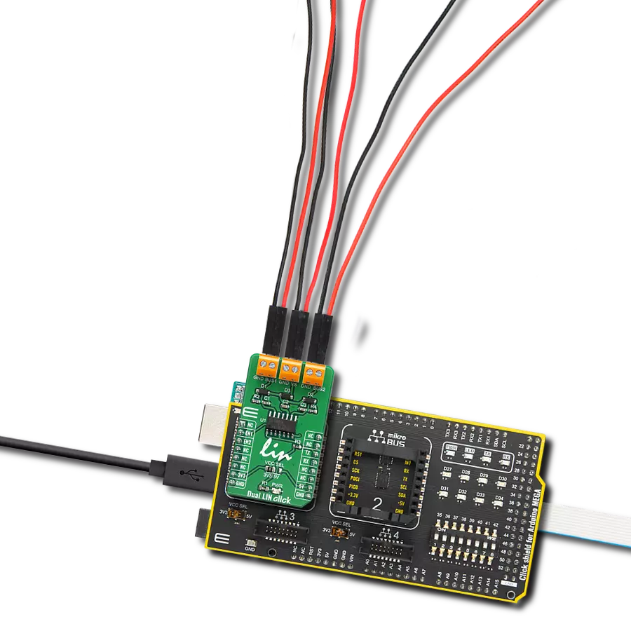
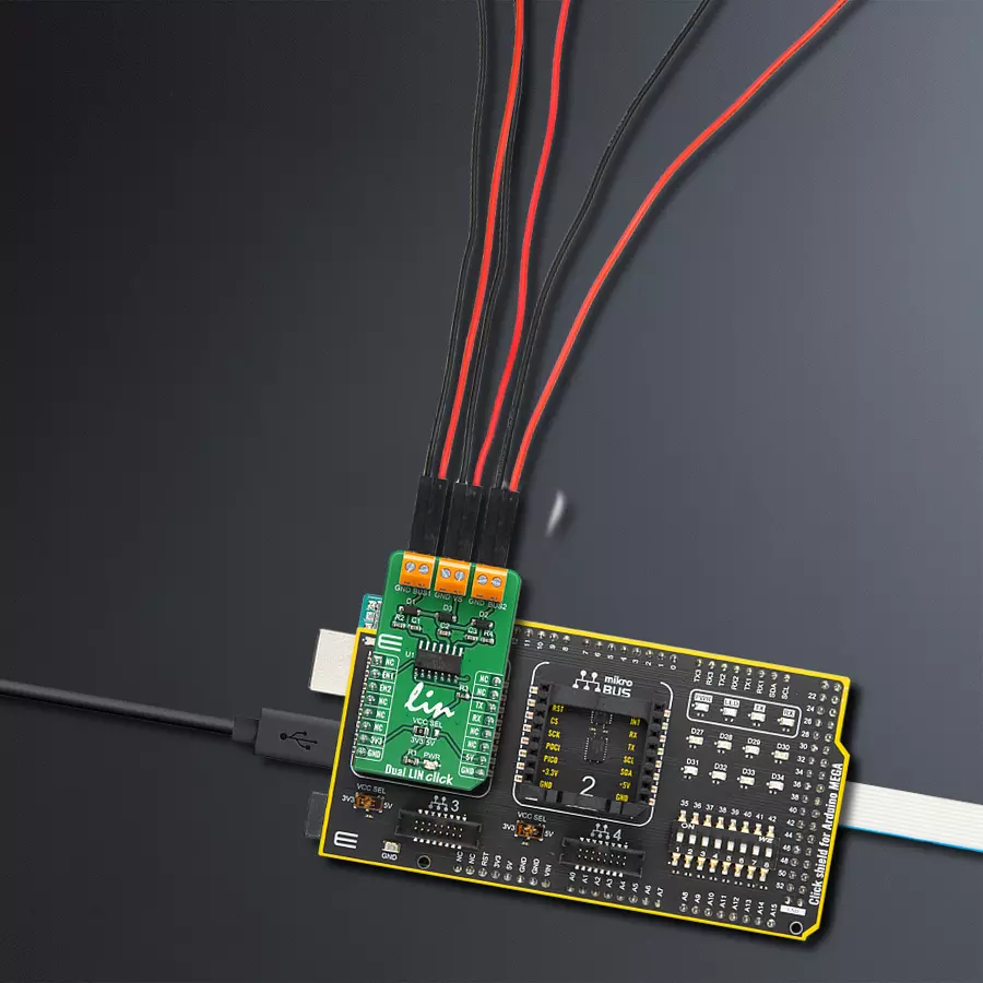
Dual LIN Click is based on the TLE7268, a dual transceiver for the Local Interconnect Network (LIN) from Infineon with integrated wake-up and protection features. The Dual LIN click is designed for in-vehicle networks using data transmission rates up to 20 kbps. Dual LIN click includes two independent transceivers that operate as bus drivers between the protocol controller and physical LIN networks. The Dual LIN click communicates with the MCU by using the UART RX and TX signals. RX and TX signals are also routed to the header on the edge of the click board™ so they can be used independently of the mikroBUS™ socket. Its most important features are the fact that it is a two separate single-wire LIN transceiver bus for transmission rates up to 20 kbps and it is compliant to ISO 17987-4 and LIN Specification 2.2A. The EN1 and EN2 pins are used to enable the functionality of BUS 1 or BUS 2 of the device. When the EN1 pin is set to a HIGH logic level, the BUS 1 of the device is set to work in the normal mode, with the transmission paths from TXD to LIN and from LIN to RXD both active. When
the EN2 pin is set to a HIGH logic level, the BUS 2 of the device is set to work in the normal mode, with the transmission paths from TXD to LIN and from LIN to RXD both active. When the EN1 pin is set to a LOW state, the BUS 1 of the device is put into silent mode, depending on the TX pin state. The EN1 pin has a pull-down resistor, so it is pulled to Ground if it is left afloat. When the EN2 pin is set to a LOW state, the BUS 2 of the device is put into silent mode, depending on the TX pin state. The EN2 pin has a pull-down resistor, so it is pulled to Ground if it is left afloat. The Dual LIN click supports different modes of operation of the two transceivers for minimizing ECU current consumption in low power modes, a common INH output can be used for controlling external circuitry, for example voltage regulators. Based on the Infineon BiCMOS technology. It provides excellent ESD robustness together with very high electromagnetic compliance (EMC). The TLE7268 reaches a very low level of electromagnetic emission (EME) within a broad frequency range and independent from the battery voltage. The
TLE7268 is AEC qualified and tailored to withstand the harsh conditions of the automotive environment. Some of the key features that are incorporated in the TLE7268 are overtemperature protection, undervoltage detection. The Dual LIN click is digital I/O levels compatible with 3.3 V and 5 V microcontrollers, that it is optimized for high electromagnetic compliance (EMC) with very low electromagnetic emission and high immunity to interference. It also features two independent single-wire LIN transceivers in one device and gives out a transmission rate of up to 20 kbps. Given the features included in this transceiver, the Dual LIN click can be used for Body Control Modules (BCM) and Gateway. This Click board™ can operate with either 3.3V or 5V logic voltage levels selected via the VCC SEL jumper. This way, both 3.3V and 5V capable MCUs can use the communication lines properly. Also, this Click board™ comes equipped with a library containing easy-to-use functions and an example code that can be used as a reference for further development.

Features overview
Development board
Arduino Mega 2560 is a robust microcontroller platform built around the ATmega 2560 chip. It has extensive capabilities and boasts 54 digital input/output pins, including 15 PWM outputs, 16 analog inputs, and 4 UARTs. With a 16MHz crystal
oscillator ensuring precise timing, it offers seamless connectivity via USB, a convenient power jack, an ICSP header, and a reset button. This all-inclusive board simplifies microcontroller projects; connect it to your computer via USB or power it up
using an AC-to-DC adapter or battery. Notably, the Mega 2560 maintains compatibility with a wide range of shields crafted for the Uno, Duemilanove, or Diecimila boards, ensuring versatility and ease of integration.

Microcontroller Overview
MCU Card / MCU

Architecture
AVR
MCU Memory (KB)
256
Silicon Vendor
Microchip
Pin count
100
RAM (Bytes)
8192
You complete me!
Accessories
Click Shield for Arduino Mega comes equipped with four mikroBUS™ sockets, with two in the form of a Shuttle connector, allowing all the Click board™ devices to be interfaced with the Arduino Mega board with no effort. Featuring an AVR 8-bit microcontroller with advanced RISC architecture, 54 digital I/O pins, and Arduino™ compatibility, the Arduino Mega board offers limitless possibilities for prototyping and creating diverse applications. This board is controlled and powered conveniently through a USB connection to program and debug the Arduino Mega board efficiently out of the box, with an additional USB cable connected to the USB B port on the board. Simplify your project development with the integrated ATmega16U2 programmer and unleash creativity using the extensive I/O options and expansion capabilities. There are eight switches, which you can use as inputs, and eight LEDs, which can be used as outputs of the MEGA2560. In addition, the shield features the MCP1501, a high-precision buffered voltage reference from Microchip. This reference is selected by default over the EXT REF jumper at the bottom of the board. You can choose an external one, as you would usually do with an Arduino Mega board. There is also a GND hook for testing purposes. Four additional LEDs are PWR, LED (standard pin D13), RX, and TX LEDs connected to UART1 (mikroBUS™ 1 socket). This Click Shield also has several switches that perform functions such as selecting the logic levels of analog signals on mikroBUS™ sockets and selecting logic voltage levels of the mikroBUS™ sockets themselves. Besides, the user is offered the possibility of using any Click board™ with the help of existing bidirectional level-shifting voltage translators, regardless of whether the Click board™ operates at a 3.3V or 5V logic voltage level. Once you connect the Arduino Mega board with Click Shield for Arduino Mega, you can access hundreds of Click boards™, working with 3.3V or 5V logic voltage levels.

Used MCU Pins
mikroBUS™ mapper
Take a closer look
Click board™ Schematic

Step by step
Project assembly

Start by selecting your development board and Click board™. Begin with the Arduino Mega 2560 Rev3 as your development board.


Track your results in real time
Application Output
1. Application Output - In Debug mode, the 'Application Output' window enables real-time data monitoring, offering direct insight into execution results. Ensure proper data display by configuring the environment correctly using the provided tutorial.

2. UART Terminal - Use the UART Terminal to monitor data transmission via a USB to UART converter, allowing direct communication between the Click board™ and your development system. Configure the baud rate and other serial settings according to your project's requirements to ensure proper functionality. For step-by-step setup instructions, refer to the provided tutorial.

3. Plot Output - The Plot feature offers a powerful way to visualize real-time sensor data, enabling trend analysis, debugging, and comparison of multiple data points. To set it up correctly, follow the provided tutorial, which includes a step-by-step example of using the Plot feature to display Click board™ readings. To use the Plot feature in your code, use the function: plot(*insert_graph_name*, variable_name);. This is a general format, and it is up to the user to replace 'insert_graph_name' with the actual graph name and 'variable_name' with the parameter to be displayed.

Software Support
Library Description
This library contains API for Dual LIN Click driver.
Key functions:
duallin_bus1_status- Sets state of RST pinduallin_bus2_status- Sets state of CS pinduallin_send_command- Send command.
Open Source
Code example
The complete application code and a ready-to-use project are available through the NECTO Studio Package Manager for direct installation in the NECTO Studio. The application code can also be found on the MIKROE GitHub account.
/*!
 * \file
 * \brief DualLin Click example
 *
 * # Description
 * This example reads and processes data from Dual LIN Clicks.
 *
 * The demo application is composed of two sections :
 *
 * ## Application Init
 * Initializes driver, and sets bus.
 *
 * ## Application Task
 * Reads the received data.
 *
 * ## Additional Function
 * - duallin_process ( ) - The general process of collecting presponce
 *                                   that sends a module.
 *
 * \author MikroE Team
 *
 */
// ------------------------------------------------------------------- INCLUDES

#include "board.h"
#include "log.h"
#include "duallin.h"
#include "string.h"

#define PROCESS_COUNTER 10
#define PROCESS_RX_BUFFER_SIZE 500

#define TEXT_TO_SEND "MikroE\r\n"

// ------------------------------------------------------------------ VARIABLES

#define DEMO_APP_RECEIVER
// #define DEMO_APP_TRANSMITER

static duallin_t duallin;
static log_t logger;

static char current_rsp_buf[ PROCESS_RX_BUFFER_SIZE ];

// ------------------------------------------------------ APPLICATION FUNCTIONS

void application_init ( void )
{
    log_cfg_t log_cfg;
    duallin_cfg_t cfg;

    /**
     * Logger initialization.
     * Default baud rate: 115200
     * Default log level: LOG_LEVEL_DEBUG
     * @note If USB_UART_RX and USB_UART_TX
     * are defined as HAL_PIN_NC, you will
     * need to define them manually for log to work.
     * See @b LOG_MAP_USB_UART macro definition for detailed explanation.
     */
    LOG_MAP_USB_UART( log_cfg );
    log_init( &logger, &log_cfg );
    log_info( &logger, "---- Application Init ----" );

    //  Click initialization.

    duallin_cfg_setup( &cfg );
    DUALLIN_MAP_MIKROBUS( cfg, MIKROBUS_1 );
    duallin_init( &duallin, &cfg );

    duallin_bus1_status( &duallin, DUALLIN_PIN_STATE_HIGH );
    duallin_bus2_status( &duallin, DUALLIN_PIN_STATE_LOW );
    Delay_ms ( 100 );
}

void application_task ( void )
{
#ifdef DEMO_APP_RECEIVER
    int32_t rsp_size = duallin_generic_read( &duallin, current_rsp_buf, PROCESS_RX_BUFFER_SIZE );
    if ( rsp_size> 0)
    {
        log_printf( &logger, "%s", current_rsp_buf );
    }
#endif

#ifdef DEMO_APP_TRANSMITER
    duallin_send_command( &duallin, TEXT_TO_SEND );
    Delay_ms ( 1000 );
    Delay_ms ( 1000 );
#endif
}

int main ( void )
{
    /* Do not remove this line or clock might not be set correctly. */
    #ifdef PREINIT_SUPPORTED
    preinit();
    #endif

    application_init( );

    for ( ; ; )
    {
        application_task( );
    }

    return 0;
}

// ------------------------------------------------------------------------ END
Additional Support
Resources
Category:LIN