Experience peace of mind as you securely isolate I2C communication using CPC5902 and ATmega2560
I2C data's Fort Knox: Secure isolation, seamless communication!
Published Feb 14, 2024
Click board™
I2C Isolator 3 Click
Dev. board
Arduino Mega 2560 Rev3
Compiler
NECTO Studio
MCU
ATmega2560
Our I2C communication isolator solution shields your data from interference and noise, ensuring secure and reliable communication in sensitive applications
A
A
Hardware Overview
How does it work?
I2C Isolator 3 Click is based on the CPC5902, a dual optically isolated bidirectional logic-bus repeater from IXYS Integrated Circuits Division. It bidirectionally buffers the two I2C signals across the isolation barrier and supports I2C clock stretching while providing 3750Vrms of galvanic isolation. The buffered signals will always return to their proper value after a transient interruption on either side. Unlike competitive magnetically isolated digital isolators, transformers, or capacitive isolators, the CPC5902 doesn’t need to be clocked periodically to sustain the logic states. Besides, it offers glitch-free operation, excellent reliability, and a very long operational life. If different supply voltage levels are used at each power supply side, it can also function as a logic
level translator for levels as low as 2.7V or as high as 5.5V. This optically coupled I2C bus repeater is ideal for Power-over-Ethernet (PoE) applications, buffering and isolating the clock and data signals between the host controller and the Power Supply Equipment (PSE) controller. Additional applications include a power supply high-side interface, an I2C bus length extender, and isolated signal monitoring and control. An extensive operational power supply range of 2.7V to 5.5V enables I2C logic-level translation applications. I2C Isolator 3 Click communicates with MCU using the standard I2C 2-Wire interface and supports both Standard and Fast Mode with a transfer rate of up to 400kbps. The CPC5902 is also fully compatible with any single or double-wire bus in the
frequency range from 0 Hz to 500 kHz, corresponding to a 400 kbps transfer rate for the I2C bus. It also possesses two terminals labeled as VIN and I2C at the bottom of the Click board™, where VIN represents the B-side power supply of the repeater, while the other I2C corresponds to the isolated bidirectional logic-bus terminal. This Click board™ can operate with either 3.3V or 5V logic voltage levels selected via the VCC SEL jumper. This way, both 3.3V and 5V capable MCUs can use the communication lines properly. Also, this Click board™ comes equipped with a library containing easy-to-use functions and an example code that can be used as a reference for further development.

Features overview
Development board
Arduino Mega 2560 is a robust microcontroller platform built around the ATmega 2560 chip. It has extensive capabilities and boasts 54 digital input/output pins, including 15 PWM outputs, 16 analog inputs, and 4 UARTs. With a 16MHz crystal
oscillator ensuring precise timing, it offers seamless connectivity via USB, a convenient power jack, an ICSP header, and a reset button. This all-inclusive board simplifies microcontroller projects; connect it to your computer via USB or power it up
using an AC-to-DC adapter or battery. Notably, the Mega 2560 maintains compatibility with a wide range of shields crafted for the Uno, Duemilanove, or Diecimila boards, ensuring versatility and ease of integration.

Microcontroller Overview
MCU Card / MCU

Architecture
AVR
MCU Memory (KB)
256
Silicon Vendor
Microchip
Pin count
100
RAM (Bytes)
8192
You complete me!
Accessories
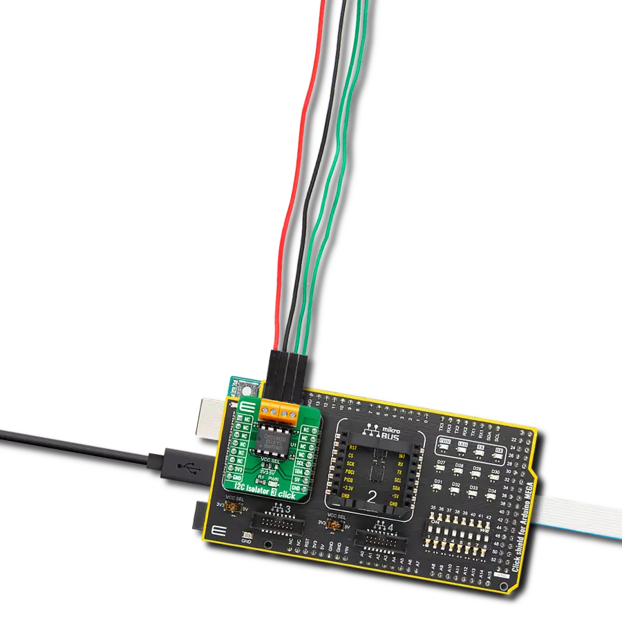
Click Shield for Arduino Mega comes equipped with four mikroBUS™ sockets, with two in the form of a Shuttle connector, allowing all the Click board™ devices to be interfaced with the Arduino Mega board with no effort. Featuring an AVR 8-bit microcontroller with advanced RISC architecture, 54 digital I/O pins, and Arduino™ compatibility, the Arduino Mega board offers limitless possibilities for prototyping and creating diverse applications. This board is controlled and powered conveniently through a USB connection to program and debug the Arduino Mega board efficiently out of the box, with an additional USB cable connected to the USB B port on the board. Simplify your project development with the integrated ATmega16U2 programmer and unleash creativity using the extensive I/O options and expansion capabilities. There are eight switches, which you can use as inputs, and eight LEDs, which can be used as outputs of the MEGA2560. In addition, the shield features the MCP1501, a high-precision buffered voltage reference from Microchip. This reference is selected by default over the EXT REF jumper at the bottom of the board. You can choose an external one, as you would usually do with an Arduino Mega board. There is also a GND hook for testing purposes. Four additional LEDs are PWR, LED (standard pin D13), RX, and TX LEDs connected to UART1 (mikroBUS™ 1 socket). This Click Shield also has several switches that perform functions such as selecting the logic levels of analog signals on mikroBUS™ sockets and selecting logic voltage levels of the mikroBUS™ sockets themselves. Besides, the user is offered the possibility of using any Click board™ with the help of existing bidirectional level-shifting voltage translators, regardless of whether the Click board™ operates at a 3.3V or 5V logic voltage level. Once you connect the Arduino Mega board with Click Shield for Arduino Mega, you can access hundreds of Click boards™, working with 3.3V or 5V logic voltage levels.

Used MCU Pins
mikroBUS™ mapper
Take a closer look
Click board™ Schematic

Step by step
Project assembly

Start by selecting your development board and Click board™. Begin with the Arduino Mega 2560 Rev3 as your development board.


Track your results in real time
Application Output
1. Application Output - In Debug mode, the 'Application Output' window enables real-time data monitoring, offering direct insight into execution results. Ensure proper data display by configuring the environment correctly using the provided tutorial.

2. UART Terminal - Use the UART Terminal to monitor data transmission via a USB to UART converter, allowing direct communication between the Click board™ and your development system. Configure the baud rate and other serial settings according to your project's requirements to ensure proper functionality. For step-by-step setup instructions, refer to the provided tutorial.

3. Plot Output - The Plot feature offers a powerful way to visualize real-time sensor data, enabling trend analysis, debugging, and comparison of multiple data points. To set it up correctly, follow the provided tutorial, which includes a step-by-step example of using the Plot feature to display Click board™ readings. To use the Plot feature in your code, use the function: plot(*insert_graph_name*, variable_name);. This is a general format, and it is up to the user to replace 'insert_graph_name' with the actual graph name and 'variable_name' with the parameter to be displayed.

Software Support
Library Description
This library contains API for I2C Isolator 3 Click driver.
Key functions:
i2cisolator3_send_cmd- This function sends the desired command to a remote device wired with CPC5902i2cisolator3_write_byte- This function writes the byte of data to the targeted 8-bit register address of the remote device wired with CPC5902i2cisolator3_read_byte- This function read a the byte of data from the targeted 8-bit register address of the remote device wired with CPC5902
Open Source
Code example
The complete application code and a ready-to-use project are available through the NECTO Studio Package Manager for direct installation in the NECTO Studio. The application code can also be found on the MIKROE GitHub account.
/*!
 * @file main.c
 * @brief I2CIsolator3 Click example
 *
 * # Description
 * This is an example that demonstrates the use of the I2C Isolator 3 Click board. In this example, we measure temperature
 * from the Thermo 20 Click connected to the I2C Isolator 3 Click board.
 *
 * The demo application is composed of two sections :
 *
 * ## Application Init
 * Initializes I2C and start to write log. Initialization driver enables - I2C,
 * set I2C slave address of the Thermo 20 Click, performs software reset, also write log.
 *
 * ## Application Task
 * In this example via Thermo 20 Click we get the data processed by the function. When the function processes the data, we get
 * the temperature information. All data logs write on USB UART changes every 3 sec.
 *
 * Additional Functions :
 * - void calculate_temperature( ) - Calculate temperature in degrees Celsius.
 *
 * @author Jelena Milosavljevic
 *
 */

#include "board.h"
#include "log.h"
#include "i2cisolator3.h"

static i2cisolator3_t i2cisolator3;
static log_t logger;
static float temperature;
static char log_text[ 50 ];

void calculate_temperature ( ) {
    uint16_t res_adc;
    uint8_t rx_buf[ 3 ];

    i2cisolator3_burst_read ( &i2cisolator3, I2CISOLATOR3_THERMO20_CMD_READ_ADC, rx_buf, 3 );

    res_adc = rx_buf[ 0 ];
    res_adc <<= 8;
    res_adc |= rx_buf[ 1 ];

    temperature = ( float ) res_adc;
    temperature /= 65535.0;
    temperature *= 165.0;
    temperature -= 40.0;
}

void application_init ( void ) {
    log_cfg_t log_cfg;                         /**< Logger config object. */
    i2cisolator3_cfg_t i2cisolator3_cfg;       /**< Click config object. */

    /**
     * Logger initialization.
     * Default baud rate: 115200
     * Default log level: LOG_LEVEL_DEBUG
     * @note If USB_UART_RX and USB_UART_TX
     * are defined as HAL_PIN_NC, you will
     * need to define them manually for log to work.
     * See @b LOG_MAP_USB_UART macro definition for detailed explanation.
     */
    LOG_MAP_USB_UART( log_cfg );
    log_init( &logger, &log_cfg );
    log_info( &logger, " Application Init " );

    // Click initialization.
    i2cisolator3_cfg_setup( &i2cisolator3_cfg );
    I2CISOLATOR3_MAP_MIKROBUS( i2cisolator3_cfg, MIKROBUS_1 );
    err_t init_flag = i2cisolator3_init( &i2cisolator3, &i2cisolator3_cfg );
    if ( I2C_MASTER_ERROR == init_flag ) {

        log_error( &logger, " Application Init Error. " );
        log_info( &logger, " Please, run program again... " );

        for ( ; ; );
    }
    log_printf( &logger, "  Driver Init. Done  \r\n" );
    log_printf( &logger, "  Set I2C Slave Address   \r\n" );
    log_printf( &logger, "  of the Thermo 20 Click   \r\n" );
    Delay_ms ( 100 );

    log_printf( &logger, "--------------------------\r\n" );
    log_printf( &logger, "      Software Reset      \r\n" );
    i2cisolator3_send_cmd(  &i2cisolator3, I2CISOLATOR3_THERMO20_CMD_RESET );
    Delay_ms ( 100 );

    log_printf( &logger, "--------------------------\r\n" );
    log_printf( &logger, "     Start Measuring      \r\n" );
    log_printf( &logger, "--------------------------\r\n" );
    Delay_ms ( 100 );

    log_info( &logger, " Application Task \r\n" );
}

void application_task ( void ) {
    i2cisolator3_send_cmd( &i2cisolator3, I2CISOLATOR3_THERMO20_CMD_CONVERSION );
    Delay_ms ( 100 );

    calculate_temperature( );

    log_printf( &logger, "Temperature : %.2f \r\n", temperature );
    Delay_ms ( 1000 );
    Delay_ms ( 1000 );
    Delay_ms ( 1000 );
}

int main ( void )
{
    /* Do not remove this line or clock might not be set correctly. */
    #ifdef PREINIT_SUPPORTED
    preinit();
    #endif

    application_init( );

    for ( ; ; )
    {
        application_task( );
    }

    return 0;
}

// ------------------------------------------------------------------------ END
Additional Support
Resources
Category:I2C