Convert high-voltage industrial signals to logic levels with MAX22196 and ATmega2560
High-performance octal industrial sink/source digital input
Published Apr 29, 2024
Click board™
DIGI IN 2 Click
Dev. board
Arduino Mega 2560 Rev3
Compiler
NECTO Studio
MCU
ATmega2560
Safely interface with high-voltage industrial signals and convert them to logic levels for controlling machinery and processes.
A
A
Hardware Overview
How does it work?
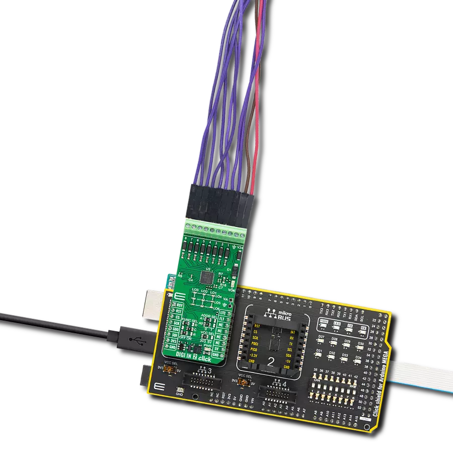
DIGI IN 2 Click is based on the MAX22196, a high-performance octal industrial sink/source digital input IC from Analog Devices. This IC converts eight high-voltage (8V-24V) industrial inputs across channels 1 to 8 into standard logic-level outputs. It incorporates a serial interface for configuring and reading data in a serialized format via SPI. Each input channel can be individually set to operate as sinking (P-type) or sourcing (N-type), with built-in current limiters to reduce power wastage while adhering to the IEC 61131-2 standards. This Click board™ is ideal for various applications, including Programmable Logic Controllers (PLC), factory automation, and process control systems. A distinctive feature of the MAX22196 is its ability to meet IEC 61131-2 Type 1/3 or Type 2 digital input requirements using a single resistor (R7) set at 12kΩ. The device offers flexibility by allowing the users to turn off current sinks or sources. Furthermore, each input channel has a customizable glitch/debounce filter and an optional 16-bit down-counter for enhanced input signal processing. The MAX22196 can draw power from a field supply ranging from 8V to 24V, including a
green LED (VOK), to indicate the presence of a stable field supply. An on-chip 5V linear regulator is another hallmark of the MAX22196, capable of delivering up to 20mA of load current to the VA header, which is left unpopulated. This on-chip regulator can be enabled via the FUNC SEL "R" jumper by placing its position from OFF to ON state. While it's in the OFF position, the VA terminal presents a 5V linear regulator output, and the ON position presents a supply input powered by mikroBUS power rail™ (3.3V or 5V). Regarding communication, the DIGI IN 2 Click interfaces with the host MCU through SPI to perform input data reading, diagnostic data acquisition, and register configuration at speeds up to 12MHz. The voltages at the 1-8 input terminals are compared against internal references to determine whether the field binary output sensor is ON (logic 1) or OFF (logic 0). All eight inputs are simultaneously latched by the assertion of either latch LTC or CS pins, and the data is made available in a serialized form through the SPI. Notably, the MAX22196 can address up to four devices on a shared SPI bus using ADDR SEL jumpers for direct access, and it
supports daisy-chaining through the FUNC SEL "D" jumper. The MAX22196 also features a fault indicator (FLT pin) for communicating various operational errors to the host MCU, including power supply undervoltage, overtemperature conditions, and CRC errors. The READY RDY signal confirms that the MAX22196 is powered on and operational. CRC error detection is enabled by default for enhanced data integrity, which is particularly beneficial in both addressable and daisy-chain SPI configurations. To visually present the status of its digital inputs, the board is equipped with a 3x3 yellow LED driver crossbar matrix. The ninth LED, positioned in the lower-left corner, mirrors the functionality of the VOK LED, providing a quick visual reference for the board's operational status. This Click board™ can operate with either 3.3V or 5V logic voltage levels selected via the VCC SEL jumper. This way, both 3.3V and 5V capable MCUs can use the communication lines properly. Also, this Click board™ comes equipped with a library containing easy-to-use functions and an example code that can be used as a reference for further development.

Features overview
Development board
Arduino Mega 2560 is a robust microcontroller platform built around the ATmega 2560 chip. It has extensive capabilities and boasts 54 digital input/output pins, including 15 PWM outputs, 16 analog inputs, and 4 UARTs. With a 16MHz crystal
oscillator ensuring precise timing, it offers seamless connectivity via USB, a convenient power jack, an ICSP header, and a reset button. This all-inclusive board simplifies microcontroller projects; connect it to your computer via USB or power it up
using an AC-to-DC adapter or battery. Notably, the Mega 2560 maintains compatibility with a wide range of shields crafted for the Uno, Duemilanove, or Diecimila boards, ensuring versatility and ease of integration.

Microcontroller Overview
MCU Card / MCU

Architecture
AVR
MCU Memory (KB)
256
Silicon Vendor
Microchip
Pin count
100
RAM (Bytes)
8192
You complete me!
Accessories
Click Shield for Arduino Mega comes equipped with four mikroBUS™ sockets, with two in the form of a Shuttle connector, allowing all the Click board™ devices to be interfaced with the Arduino Mega board with no effort. Featuring an AVR 8-bit microcontroller with advanced RISC architecture, 54 digital I/O pins, and Arduino™ compatibility, the Arduino Mega board offers limitless possibilities for prototyping and creating diverse applications. This board is controlled and powered conveniently through a USB connection to program and debug the Arduino Mega board efficiently out of the box, with an additional USB cable connected to the USB B port on the board. Simplify your project development with the integrated ATmega16U2 programmer and unleash creativity using the extensive I/O options and expansion capabilities. There are eight switches, which you can use as inputs, and eight LEDs, which can be used as outputs of the MEGA2560. In addition, the shield features the MCP1501, a high-precision buffered voltage reference from Microchip. This reference is selected by default over the EXT REF jumper at the bottom of the board. You can choose an external one, as you would usually do with an Arduino Mega board. There is also a GND hook for testing purposes. Four additional LEDs are PWR, LED (standard pin D13), RX, and TX LEDs connected to UART1 (mikroBUS™ 1 socket). This Click Shield also has several switches that perform functions such as selecting the logic levels of analog signals on mikroBUS™ sockets and selecting logic voltage levels of the mikroBUS™ sockets themselves. Besides, the user is offered the possibility of using any Click board™ with the help of existing bidirectional level-shifting voltage translators, regardless of whether the Click board™ operates at a 3.3V or 5V logic voltage level. Once you connect the Arduino Mega board with Click Shield for Arduino Mega, you can access hundreds of Click boards™, working with 3.3V or 5V logic voltage levels.

Used MCU Pins
mikroBUS™ mapper
Take a closer look
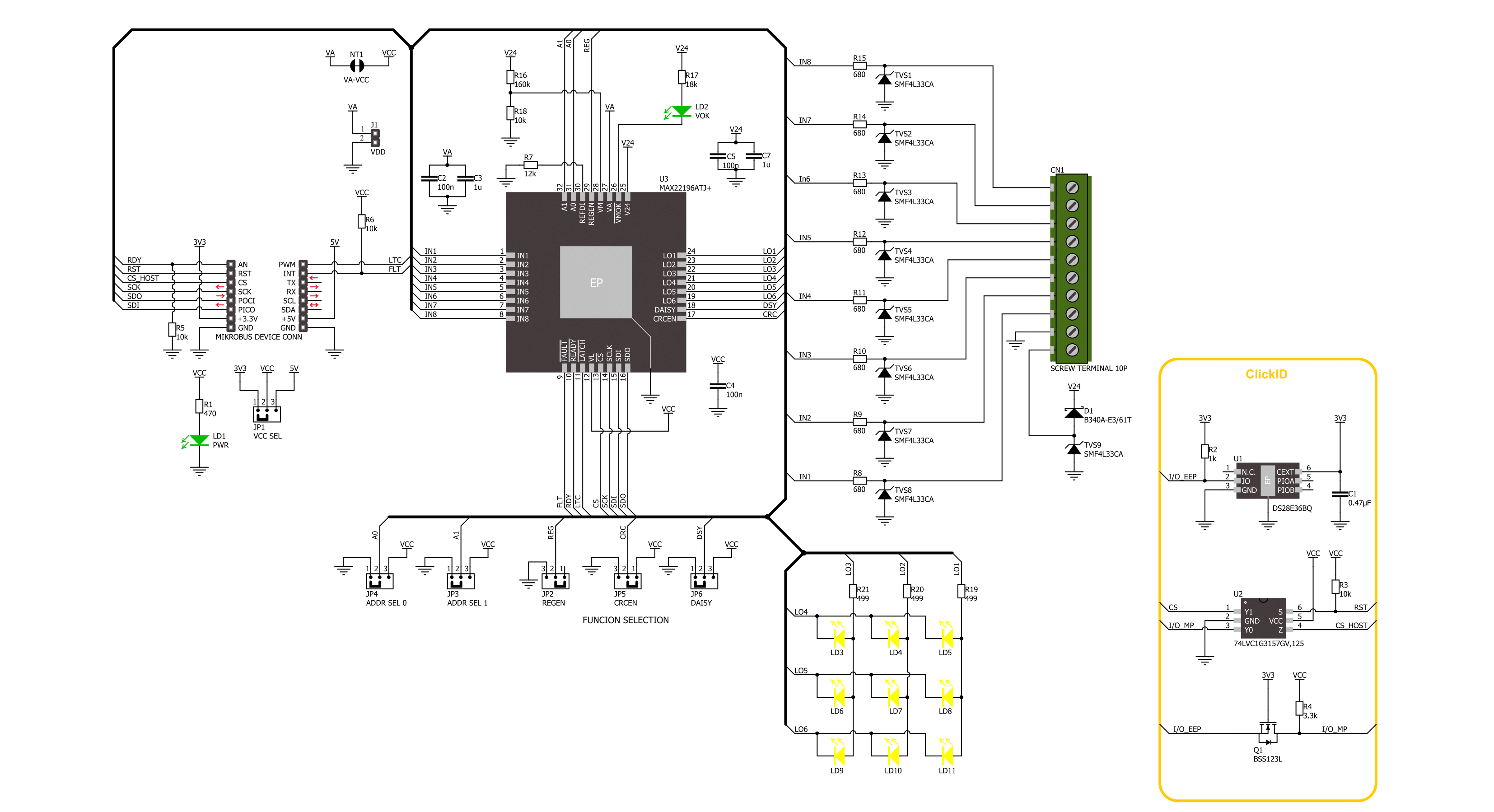
Click board™ Schematic
Step by step
Project assembly

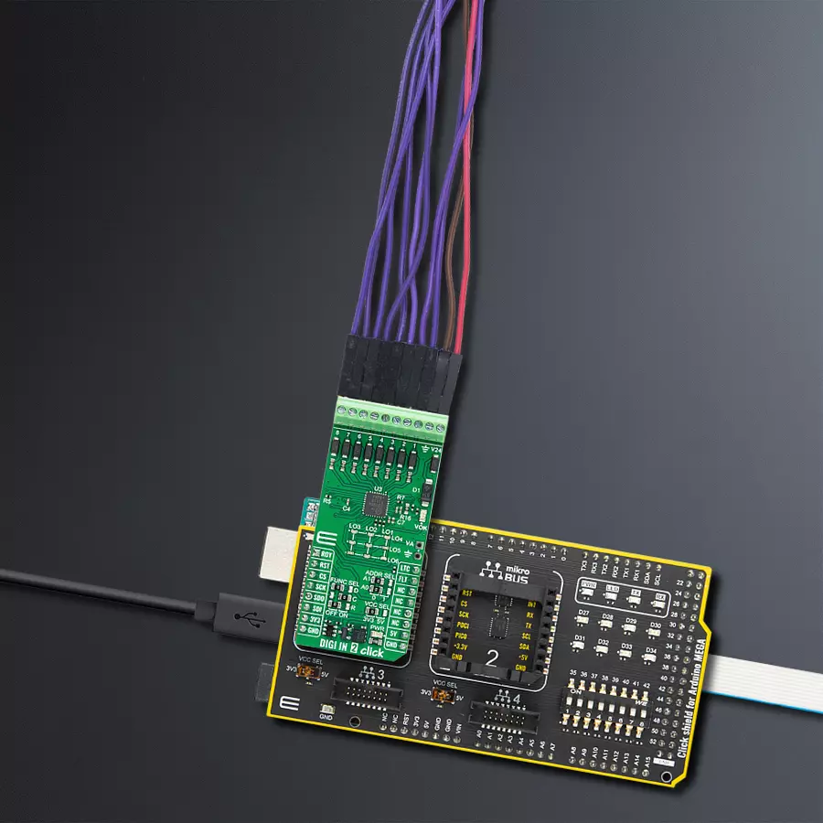
Start by selecting your development board and Click board™. Begin with the Arduino Mega 2560 Rev3 as your development board.


Software Support
Library Description
This library contains API for DIGI IN 2 Click driver.
Key functions:
digiin2_get_flt_pin- This function is used to get state of the FLT pindigiin2_write_reg- This function is used to write data into the selected register by using SPI serial interfacedigiin2_read_reg- This function reads a data byte from the selected register by using SPI serial interface
Open Source
Code example
The complete application code and a ready-to-use project are available through the NECTO Studio Package Manager for direct installation in the NECTO Studio. The application code can also be found on the MIKROE GitHub account.
/*!
 * @file main.c
 * @brief DIGI IN 2 Click example
 *
 * # Description
 * This example demonstrates the use of DIGI IN 2 Click board by reading and
 * displaying the state of the channels.
 *
 * The demo application is composed of two sections :
 *
 * ## Application Init
 * Initializes the driver, performs the Click default configuration.
 *
 * ## Application Task
 * Reads and displays on the USB UART the channel state every second.
 *
 * @author Stefan Ilic
 *
 */

#include "board.h"
#include "log.h"
#include "digiin2.h"

static digiin2_t digiin2;
static log_t logger;

void application_init ( void )
{
    log_cfg_t log_cfg;  /**< Logger config object. */
    digiin2_cfg_t digiin2_cfg;  /**< Click config object. */

    /**
     * Logger initialization.
     * Default baud rate: 115200
     * Default log level: LOG_LEVEL_DEBUG
     * @note If USB_UART_RX and USB_UART_TX
     * are defined as HAL_PIN_NC, you will
     * need to define them manually for log to work.
     * See @b LOG_MAP_USB_UART macro definition for detailed explanation.
     */
    LOG_MAP_USB_UART( log_cfg );
    log_init( &logger, &log_cfg );
    log_info( &logger, " Application Init " );

    // Click initialization.
    digiin2_cfg_setup( &digiin2_cfg );
    DIGIIN2_MAP_MIKROBUS( digiin2_cfg, MIKROBUS_1 );
    if ( SPI_MASTER_ERROR == digiin2_init( &digiin2, &digiin2_cfg ) )
    {
        log_error( &logger, " Communication init." );
        for ( ; ; );
    }

    if ( DIGIIN2_ERROR == digiin2_default_cfg ( &digiin2 ) )
    {
        log_error( &logger, " Default configuration." );
        for ( ; ; );
    }

    log_info( &logger, " Application Task " );
}

void application_task ( void )
{
    uint8_t channel_data = 0;

    digiin2_pulse_latch( &digiin2 );

    if ( DIGIIN2_OK == digiin2_read_reg( &digiin2, DIGIIN2_REG_DISTATE, &channel_data ) )
    {
        if ( channel_data & DIGIIN2_CHANNEL_1_MASK )
        {
            log_printf( &logger, "Channel 1 counter: HIGH \r\n" );
        }
        else
        {
            log_printf( &logger, "Channel 1 counter: LOW \r\n" );
        }
        if ( channel_data & DIGIIN2_CHANNEL_2_MASK )
        {
            log_printf( &logger, "Channel 2 counter: HIGH \r\n" );
        }
        else
        {
            log_printf( &logger, "Channel 2 counter: LOW \r\n" );
        }
        if ( channel_data & DIGIIN2_CHANNEL_3_MASK )
        {
            log_printf( &logger, "Channel 3 counter: HIGH \r\n" );
        }
        else
        {
            log_printf( &logger, "Channel 3 counter: LOW \r\n" );
        }
        if ( channel_data & DIGIIN2_CHANNEL_4_MASK )
        {
            log_printf( &logger, "Channel 4 counter: HIGH \r\n" );
        }
        else
        {
            log_printf( &logger, "Channel 4 counter: LOW \r\n" );
        }
        if ( channel_data & DIGIIN2_CHANNEL_5_MASK )
        {
            log_printf( &logger, "Channel 5 counter: HIGH \r\n" );
        }
        else
        {
            log_printf( &logger, "Channel 5 counter: LOW \r\n" );
        }
        if ( channel_data & DIGIIN2_CHANNEL_6_MASK )
        {
            log_printf( &logger, "Channel 6 counter: HIGH \r\n" );
        }
        else
        {
            log_printf( &logger, "Channel 6 counter: LOW \r\n" );
        }
        if ( channel_data & DIGIIN2_CHANNEL_7_MASK )
        {
            log_printf( &logger, "Channel 7 counter: HIGH \r\n" );
        }
        else
        {
            log_printf( &logger, "Channel 7 counter: LOW \r\n" );
        }
        if ( channel_data & DIGIIN2_CHANNEL_8_MASK )
        {
            log_printf( &logger, "Channel 8 counter: HIGH \r\n" );
        }
        else
        {
            log_printf( &logger, "Channel 8 counter: LOW \r\n" );
        }
        log_printf( &logger, "- - - - - - - - - - - - - -\r\n" );
    }
    else
    {
        log_error( &logger, " Read error." );
    }

    if ( DIGIIN2_PIN_STATE_HIGH == digiin2_get_flt_pin( &digiin2 ) )
    {
        uint8_t flt_data = 0;
        digiin2_read_reg( &digiin2, DIGIIN2_REG_FAULT, &flt_data );
        log_printf( &logger, "Fault1 data: 0x%.2X \r\n", ( uint16_t ) flt_data );
        digiin2_read_reg( &digiin2, DIGIIN2_REG_FAULT2, &flt_data );
        log_printf( &logger, "Fault2 data: 0x%.2X \r\n", ( uint16_t ) flt_data );
        log_printf( &logger, "- - - - - - - - - - - - - -\r\n" );
    }

    Delay_ms ( 1000 );
}

int main ( void )
{
    /* Do not remove this line or clock might not be set correctly. */
    #ifdef PREINIT_SUPPORTED
    preinit();
    #endif

    application_init( );

    for ( ; ; )
    {
        application_task( );
    }

    return 0;
}

// ------------------------------------------------------------------------ END
Additional Support
Resources
Category:Port expander


