Achieve versatile motion detection for diverse needs with EKMC1603111 and ATmega2560
Infrared intelligence: Pyroelectric motion at your service!
Published Feb 14, 2024
Click board™
Motion 4 Click
Dev. board
Arduino Mega 2560 Rev3
Compiler
NECTO Studio
MCU
ATmega2560
Our purpose is to empower homes and businesses with the unmatched convenience and efficiency of PIR motion sensors, creating smart and responsive environments that adapt seamlessly to the needs of occupants
A
A
Hardware Overview
How does it work?
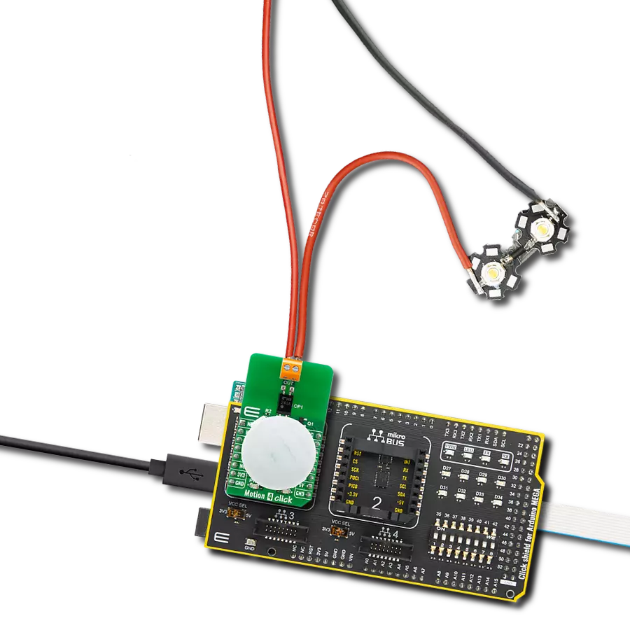
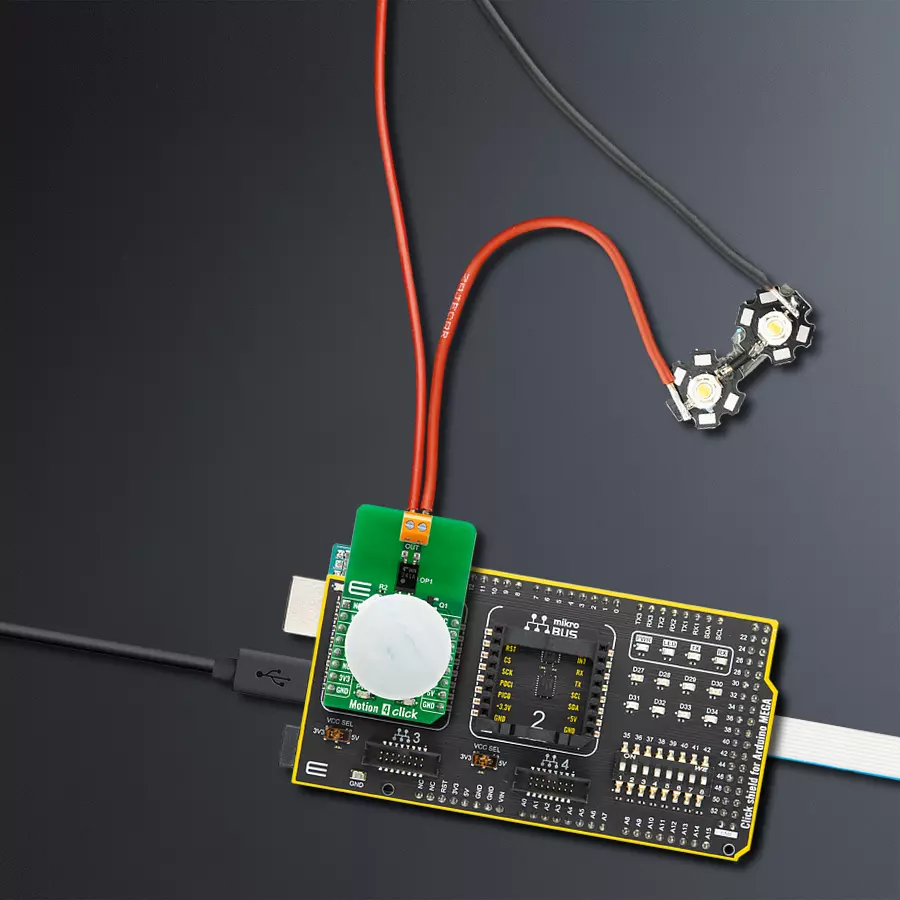
Motion 4 Click is based on EKMC1603111, a PIR motion sensor from Panasonic used as a human motion detector. This PIR sensor can detect changes in the amount of infrared radiation impinging upon it, which varies depending on the temperature and surface characteristics of the objects in front of the sensor. Detection performance of EKMC1603111 at ambient temperature of 25°C with temperature difference higher than 4°C is up to 12m. Angle detection area with 92 detection zones is 102°(±51°)horizontal and 92°(±46°)vertical. Output from PIR sensor is feed into buffer and then photorelay alowing users to directly control with galvanic isolation from sensor and MCU electronic devices such as lights, motors, gates, and more. The TLP241A photorelay
is able to effectively replace traditionally used mechanical relays, bringing up the full set of inherited benefits: virtually unlimited number of cycles since there are no moving parts that would wear off, no bouncing effect on the output contacts, high resistance to mechanical shock and environmental influence, low current required for the activation, constant resistance since no carbon and rust can build up on contacts, there is no sparking or electric arc forming while operated, compact size, higher isolation voltage, and so on. When an object, such as a person, passes in front of the background, such as a wall, the temperature at that point in the sensor's field of view will rise from room temperature to body temperature, and then back again. The sensor converts the
resulting change in the incoming infrared radiation into a change in the output voltage, and this triggers the detection. Objects of similar temperature but different surface characteristics may also have a different infrared emission pattern, and thus moving them with respect to the background may trigger the detector as well. In some cases, going back and forth towards the sensor (parallel movement to the axis Z), may not be detected. Difficulty in sensing the heat source is that glass, acrylic or similar materials standing between the target and the sensor may not allow a correct transmission of infrared rays and also non-movement or quick movements of the heat source inside the detection area.


Features overview
Development board
Arduino Mega 2560 is a robust microcontroller platform built around the ATmega 2560 chip. It has extensive capabilities and boasts 54 digital input/output pins, including 15 PWM outputs, 16 analog inputs, and 4 UARTs. With a 16MHz crystal
oscillator ensuring precise timing, it offers seamless connectivity via USB, a convenient power jack, an ICSP header, and a reset button. This all-inclusive board simplifies microcontroller projects; connect it to your computer via USB or power it up
using an AC-to-DC adapter or battery. Notably, the Mega 2560 maintains compatibility with a wide range of shields crafted for the Uno, Duemilanove, or Diecimila boards, ensuring versatility and ease of integration.

Microcontroller Overview
MCU Card / MCU

Architecture
AVR
MCU Memory (KB)
256
Silicon Vendor
Microchip
Pin count
100
RAM (Bytes)
8192
You complete me!
Accessories
Click Shield for Arduino Mega comes equipped with four mikroBUS™ sockets, with two in the form of a Shuttle connector, allowing all the Click board™ devices to be interfaced with the Arduino Mega board with no effort. Featuring an AVR 8-bit microcontroller with advanced RISC architecture, 54 digital I/O pins, and Arduino™ compatibility, the Arduino Mega board offers limitless possibilities for prototyping and creating diverse applications. This board is controlled and powered conveniently through a USB connection to program and debug the Arduino Mega board efficiently out of the box, with an additional USB cable connected to the USB B port on the board. Simplify your project development with the integrated ATmega16U2 programmer and unleash creativity using the extensive I/O options and expansion capabilities. There are eight switches, which you can use as inputs, and eight LEDs, which can be used as outputs of the MEGA2560. In addition, the shield features the MCP1501, a high-precision buffered voltage reference from Microchip. This reference is selected by default over the EXT REF jumper at the bottom of the board. You can choose an external one, as you would usually do with an Arduino Mega board. There is also a GND hook for testing purposes. Four additional LEDs are PWR, LED (standard pin D13), RX, and TX LEDs connected to UART1 (mikroBUS™ 1 socket). This Click Shield also has several switches that perform functions such as selecting the logic levels of analog signals on mikroBUS™ sockets and selecting logic voltage levels of the mikroBUS™ sockets themselves. Besides, the user is offered the possibility of using any Click board™ with the help of existing bidirectional level-shifting voltage translators, regardless of whether the Click board™ operates at a 3.3V or 5V logic voltage level. Once you connect the Arduino Mega board with Click Shield for Arduino Mega, you can access hundreds of Click boards™, working with 3.3V or 5V logic voltage levels.

Used MCU Pins
mikroBUS™ mapper
Take a closer look
Click board™ Schematic

Step by step
Project assembly

Start by selecting your development board and Click board™. Begin with the Arduino Mega 2560 Rev3 as your development board.


Track your results in real time
Application Output
1. Application Output - In Debug mode, the 'Application Output' window enables real-time data monitoring, offering direct insight into execution results. Ensure proper data display by configuring the environment correctly using the provided tutorial.

2. UART Terminal - Use the UART Terminal to monitor data transmission via a USB to UART converter, allowing direct communication between the Click board™ and your development system. Configure the baud rate and other serial settings according to your project's requirements to ensure proper functionality. For step-by-step setup instructions, refer to the provided tutorial.

3. Plot Output - The Plot feature offers a powerful way to visualize real-time sensor data, enabling trend analysis, debugging, and comparison of multiple data points. To set it up correctly, follow the provided tutorial, which includes a step-by-step example of using the Plot feature to display Click board™ readings. To use the Plot feature in your code, use the function: plot(*insert_graph_name*, variable_name);. This is a general format, and it is up to the user to replace 'insert_graph_name' with the actual graph name and 'variable_name' with the parameter to be displayed.

Software Support
Library Description
This library contains API for Motion 4 Click driver.
Key functions:
motion4_enable- This function enables/disables motion sensor by setting EN pin statemotion4_detect_state- This function returns INT pin state
Open Source
Code example
The complete application code and a ready-to-use project are available through the NECTO Studio Package Manager for direct installation in the NECTO Studio. The application code can also be found on the MIKROE GitHub account.
/*!
 * @file main.c
 * @brief Motion 4 Click Example.
 *
 * # Description
 * This example demonstrates the use of Motion 4 Click boards.
 *
 * The demo application is composed of two sections :
 *
 * ## Application Init
 * Initializes the driver and enables the motion sensor.
 *
 * ## Application Task
 * It checks if the sensor has detected movement and therefore displays
 * the desired message on the USB UART.
 *
 * @author Jelena Milosavljevic
 *
 */
// ------------------------------------------------------------------- INCLUDES
#include "board.h"
#include "log.h"
#include "motion4.h"

// ------------------------------------------------------------------ VARIABLES

static motion4_t motion4;   /**< Motion 4 Click driver object. */
static log_t logger;    /**< Logger object. */

motion4_detect_state_t motion_state;
motion4_detect_state_t motion_old_state;
// ------------------------------------------------------ APPLICATION FUNCTIONS

void application_init ( void ) {
    log_cfg_t log_cfg;  /**< Logger config object. */
    motion4_cfg_t motion4_cfg;  /**< Click config object. */

    /**
     * Logger initialization.
     * Default baud rate: 115200
     * Default log level: LOG_LEVEL_DEBUG
     * @note If USB_UART_RX and USB_UART_TX
     * are defined as HAL_PIN_NC, you will
     * need to define them manually for log to work.
     * See @b LOG_MAP_USB_UART macro definition for detailed explanation.
     */
    LOG_MAP_USB_UART( log_cfg );
    log_init( &logger, &log_cfg );
    log_info( &logger, " Application Init " );

    // Click initialization.

    motion4_cfg_setup( &motion4_cfg );
    MOTION4_MAP_MIKROBUS( motion4_cfg, MIKROBUS_1 );
    if ( motion4_init( &motion4, &motion4_cfg ) == DIGITAL_OUT_UNSUPPORTED_PIN ) {

        log_error( &logger, " Application Init Error. " );
        log_info( &logger, " Please, run program again... " );

        for ( ; ; );
    }

    motion4_enable( &motion4, MOTION4_MODULE_ENABLE );
    Delay_ms ( 100 );
    log_printf( &logger, "The sensor is ready.\r\n" );
    log_printf( &logger, "-----------------------\r\n" );
}

void application_task ( void ) {
    uint8_t int_status;

    int_status = motion4_detect_state( &motion4 );

    if ( int_status == MOTION4_DETECT_OBJECT ) {

        log_printf( &logger, "Motion detected!\r\n" );
        log_printf( &logger, "-----------------------\r\n" );
        while ( int_status == MOTION4_DETECT_OBJECT ) {

            int_status = motion4_detect_state( &motion4 );
        }
        log_printf( &logger, "The sensor is ready.\r\n" );
        log_printf( &logger, "-----------------------\r\n" );
        Delay_ms ( 100 );
    }
}


int main ( void )
{
    /* Do not remove this line or clock might not be set correctly. */
    #ifdef PREINIT_SUPPORTED
    preinit();
    #endif

    application_init( );

    for ( ; ; )
    {
        application_task( );
    }

    return 0;
}

// ------------------------------------------------------------------------ END
Additional Support
Resources
Category:Motion


