Synchronize and secure your SPI data flow effortlessly with DCL541A01 and ATmega2560
Isolate to elevate: Transforming SPI communication with precision and power!

Published Feb 14, 2024
Click board™
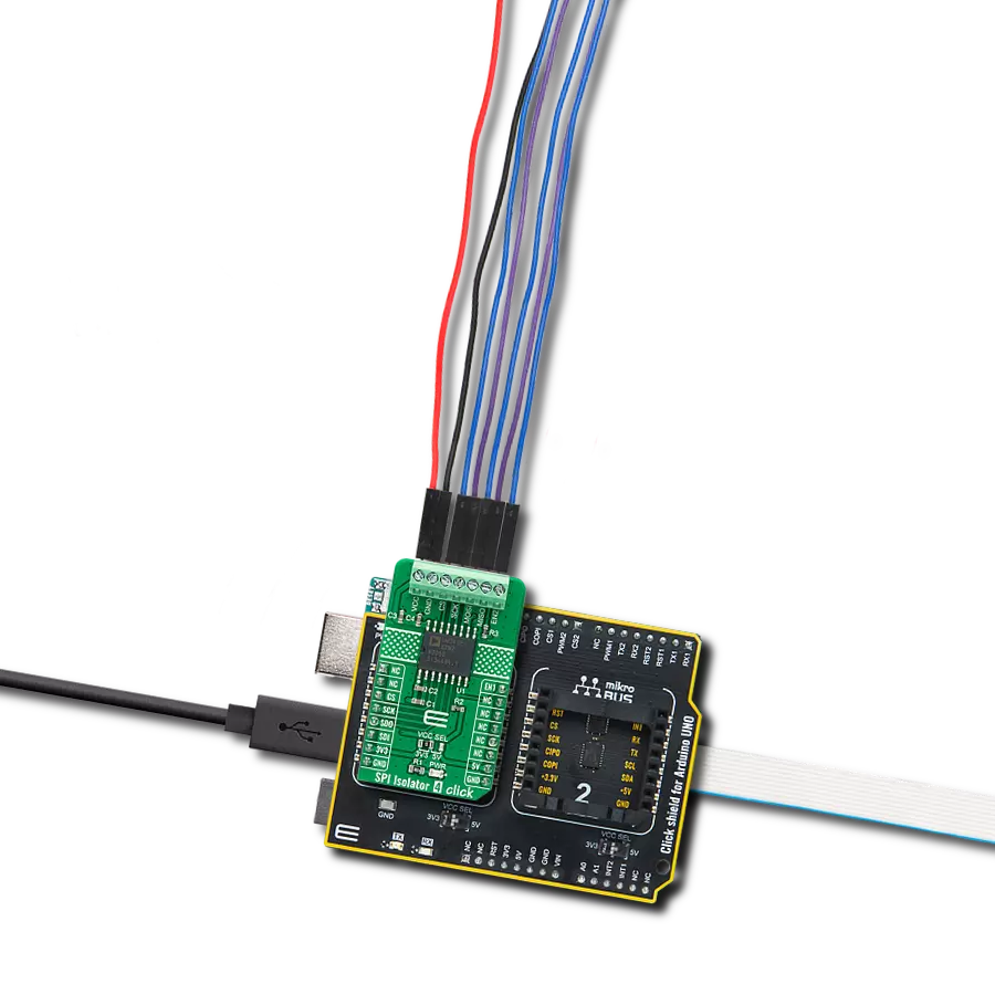
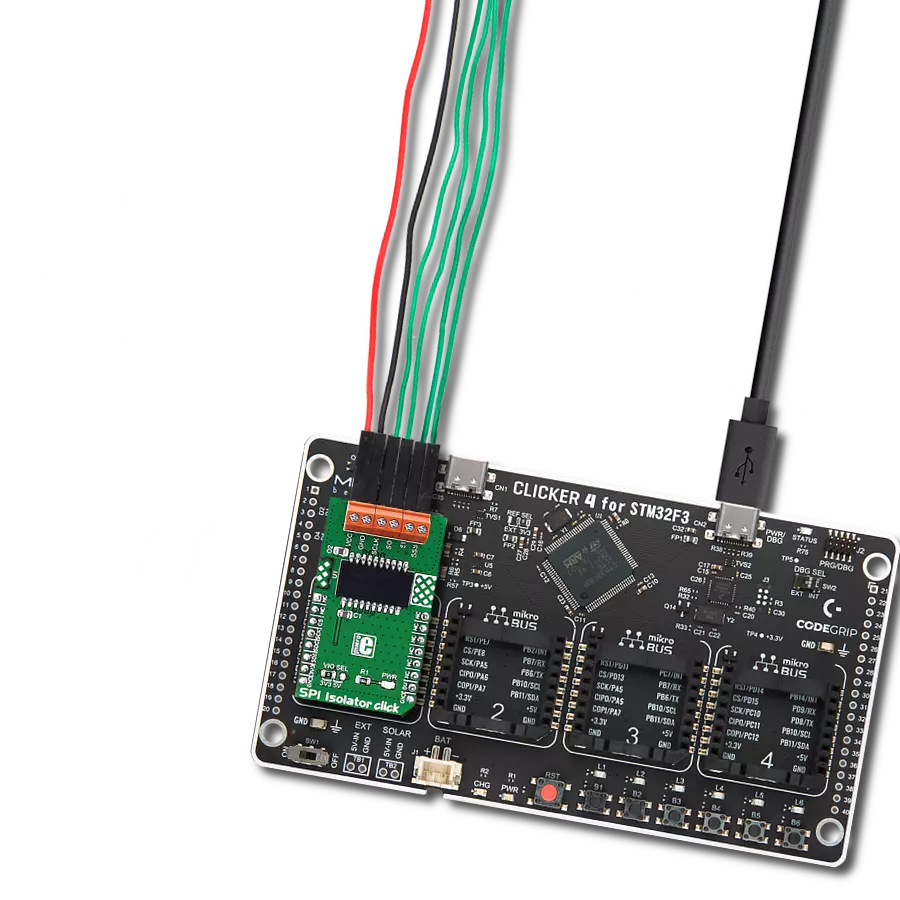
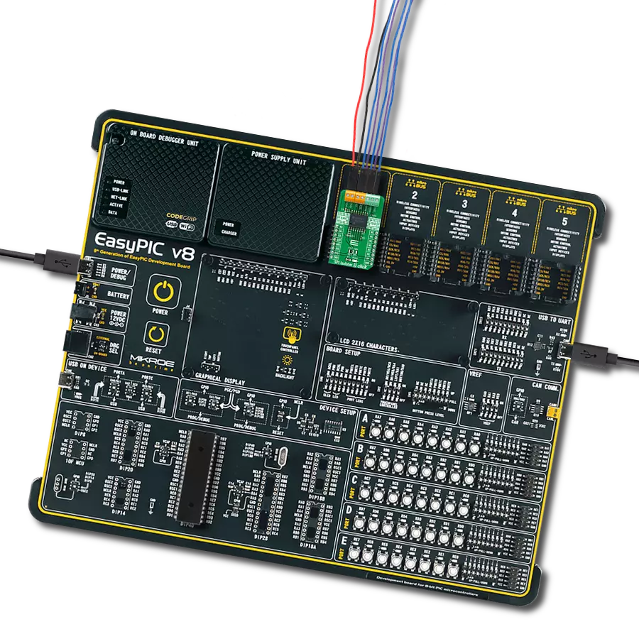
SPI Isolator 5 Click
Dev. board
Arduino Mega 2560 Rev3
Compiler
NECTO Studio
MCU
ATmega2560
Our SPI isolator ensures data integrity by providing a robust barrier against electrical noise, guaranteeing a seamless and secure serial interface.
A
A
Hardware Overview
How does it work?
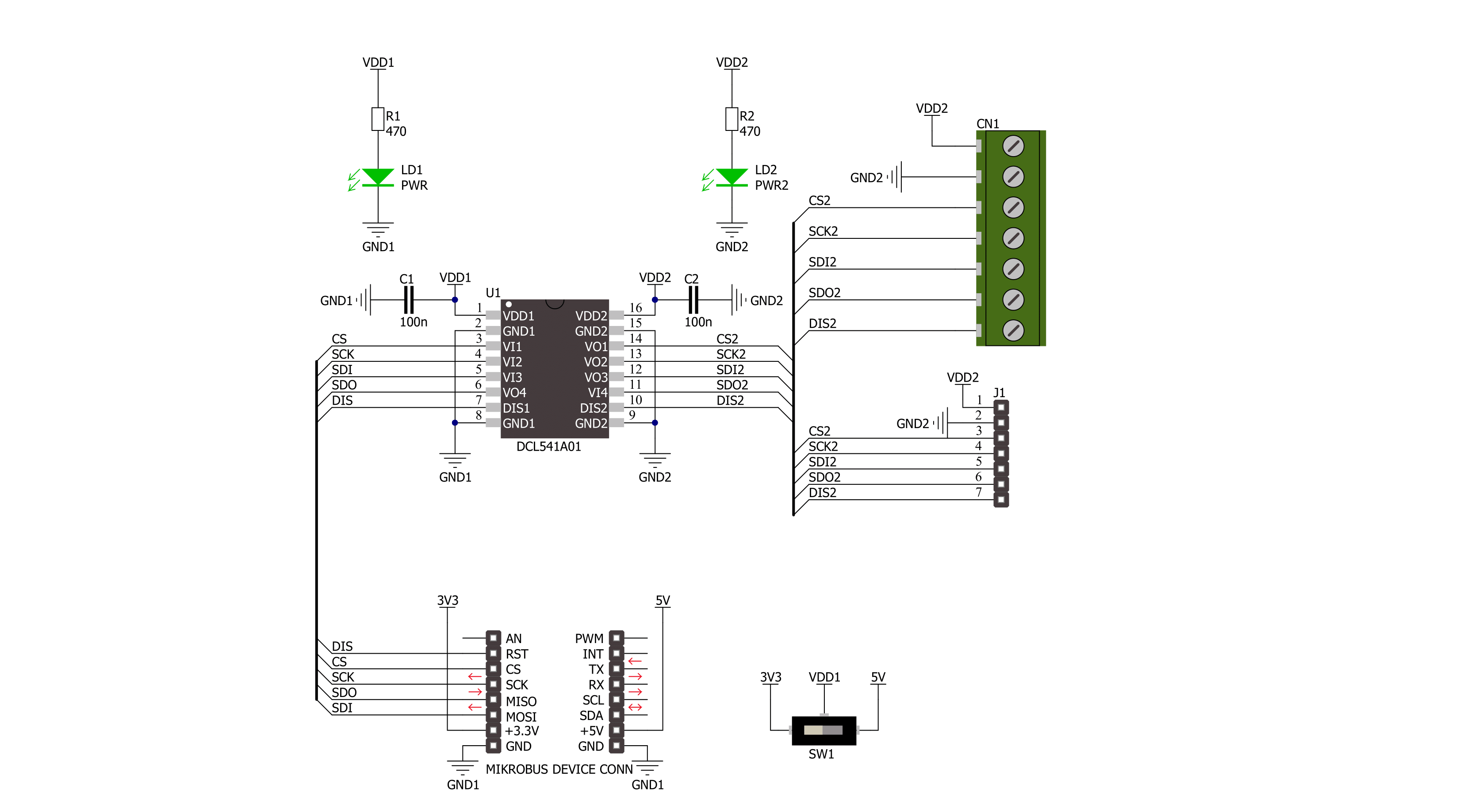
SPI Isolator 5 Click is based on the DCL541A01, a high-speed quad-channel digital isolator from Toshiba Semiconductor. The DCL541A01 stands out with its exceptional performance capabilities, made possible by leveraging Toshiba's advanced CMOS technology and a magnetic coupling structure. Not only does it meet the stringent safety standards of UL 1577 certification, but it also boasts an impressive withstand voltage rating of 5kVrms. Furthermore, its operating range spans from 2.25V to 5.5V, enabling seamless integration with lower voltage systems and facilitating voltage translation functionality across isolation barriers. With its versatility, this Click board™ is well-suited
for various applications, including industrial automation systems, motor control, inverters, and more. SPI Isolator 5 Click communicates with an MCU using the SPI serial interface with a maximum data rate of 150Mbps. The isolated lines are divided into two groups with the same lines. The first group comes in the form of 5 screw terminals, while the second forms a classic male 5-header row for easier jumper wire usage. Both groups of connectors have the same functions. You can distinguish the power VDD2 and GND2 lines from the data lines, which are CS2, SCK2, SDI2, SDO2, and DIS2. The DIS and DIS2 pins have the same function: to disable the lines from the
side of the isolator on which they are located. By setting the DIS pin to a high logic level, the input signals are disabled, and by setting it to a low logic level, they are enabled. The isolator can work with external supply voltages from 2.25V up to 5.5V, and the existence of an external power supply is easily visible using the PWR2 LED indicator. This Click board™ can operate with either 3.3V or 5V logic voltage levels selected via the VCC SEL switch. This way, both 3.3V and 5V capable MCUs can use the communication lines properly. Also, it comes equipped with a library containing functions and an example code that can be used as a reference for further development.

Features overview
Development board
Arduino Mega 2560 is a robust microcontroller platform built around the ATmega 2560 chip. It has extensive capabilities and boasts 54 digital input/output pins, including 15 PWM outputs, 16 analog inputs, and 4 UARTs. With a 16MHz crystal
oscillator ensuring precise timing, it offers seamless connectivity via USB, a convenient power jack, an ICSP header, and a reset button. This all-inclusive board simplifies microcontroller projects; connect it to your computer via USB or power it up
using an AC-to-DC adapter or battery. Notably, the Mega 2560 maintains compatibility with a wide range of shields crafted for the Uno, Duemilanove, or Diecimila boards, ensuring versatility and ease of integration.

Microcontroller Overview
MCU Card / MCU

Architecture
AVR
MCU Memory (KB)
256
Silicon Vendor
Microchip
Pin count
100
RAM (Bytes)
8192
You complete me!
Accessories
Click Shield for Arduino Mega comes equipped with four mikroBUS™ sockets, with two in the form of a Shuttle connector, allowing all the Click board™ devices to be interfaced with the Arduino Mega board with no effort. Featuring an AVR 8-bit microcontroller with advanced RISC architecture, 54 digital I/O pins, and Arduino™ compatibility, the Arduino Mega board offers limitless possibilities for prototyping and creating diverse applications. This board is controlled and powered conveniently through a USB connection to program and debug the Arduino Mega board efficiently out of the box, with an additional USB cable connected to the USB B port on the board. Simplify your project development with the integrated ATmega16U2 programmer and unleash creativity using the extensive I/O options and expansion capabilities. There are eight switches, which you can use as inputs, and eight LEDs, which can be used as outputs of the MEGA2560. In addition, the shield features the MCP1501, a high-precision buffered voltage reference from Microchip. This reference is selected by default over the EXT REF jumper at the bottom of the board. You can choose an external one, as you would usually do with an Arduino Mega board. There is also a GND hook for testing purposes. Four additional LEDs are PWR, LED (standard pin D13), RX, and TX LEDs connected to UART1 (mikroBUS™ 1 socket). This Click Shield also has several switches that perform functions such as selecting the logic levels of analog signals on mikroBUS™ sockets and selecting logic voltage levels of the mikroBUS™ sockets themselves. Besides, the user is offered the possibility of using any Click board™ with the help of existing bidirectional level-shifting voltage translators, regardless of whether the Click board™ operates at a 3.3V or 5V logic voltage level. Once you connect the Arduino Mega board with Click Shield for Arduino Mega, you can access hundreds of Click boards™, working with 3.3V or 5V logic voltage levels.

Used MCU Pins
mikroBUS™ mapper
Take a closer look
Click board™ Schematic
Step by step
Project assembly

Start by selecting your development board and Click board™. Begin with the Arduino Mega 2560 Rev3 as your development board.


Track your results in real time
Application Output
1. Application Output - In Debug mode, the 'Application Output' window enables real-time data monitoring, offering direct insight into execution results. Ensure proper data display by configuring the environment correctly using the provided tutorial.

2. UART Terminal - Use the UART Terminal to monitor data transmission via a USB to UART converter, allowing direct communication between the Click board™ and your development system. Configure the baud rate and other serial settings according to your project's requirements to ensure proper functionality. For step-by-step setup instructions, refer to the provided tutorial.

3. Plot Output - The Plot feature offers a powerful way to visualize real-time sensor data, enabling trend analysis, debugging, and comparison of multiple data points. To set it up correctly, follow the provided tutorial, which includes a step-by-step example of using the Plot feature to display Click board™ readings. To use the Plot feature in your code, use the function: plot(*insert_graph_name*, variable_name);. This is a general format, and it is up to the user to replace 'insert_graph_name' with the actual graph name and 'variable_name' with the parameter to be displayed.

Software Support
Library Description
This library contains API for SPI Isolator 5 Click driver.
Key functions:
spiisolator5_write- SPI Isolator 5 data writing function.spiisolator5_read- SPI Isolator 5 data reading function.spiisolator5_transfer- SPI Isolator 5 transfer function.
Open Source
Code example
The complete application code and a ready-to-use project are available through the NECTO Studio Package Manager for direct installation in the NECTO Studio. The application code can also be found on the MIKROE GitHub account.
/*!
 * @file main.c
 * @brief SPI Isolator 5 Click example
 *
 * # Description
 * This example demonstrates the use of SPI Isolator 5 Click board
 * by reading the manufacturer ID and device ID
 * of the connected Flash 11 Click board.
 *
 * The demo application is composed of two sections :
 *
 * ## Application Init
 * The initialization of SPI module, log UART, and additional pins.
 * After the driver init, the app performs enabling a device.
 *
 * ## Application Task
 * The demo application reads and checks the manufacturer ID and
 * device ID of the connected Flash 11 Click board.
 * Results are being sent to the UART Terminal, where you can track their changes.
 *
 * @author Nenad Filipovic
 *
 */

#include "board.h"
#include "log.h"
#include "spiisolator5.h"

#define FLASH11_CMD_GET_ID         0x90, 0x00, 0x00, 0x00, 0x00, 0x00
#define FLASH11_MANUFACTURER_ID    0x1F
#define FLASH11_DEVICE_ID          0x15

static spiisolator5_t spiisolator5;
static log_t logger;

void application_init ( void )
{
    log_cfg_t log_cfg;  /**< Logger config object. */
    spiisolator5_cfg_t spiisolator5_cfg;  /**< Click config object. */

    /**
     * Logger initialization.
     * Default baud rate: 115200
     * Default log level: LOG_LEVEL_DEBUG
     * @note If USB_UART_RX and USB_UART_TX
     * are defined as HAL_PIN_NC, you will
     * need to define them manually for log to work.
     * See @b LOG_MAP_USB_UART macro definition for detailed explanation.
     */
    LOG_MAP_USB_UART( log_cfg );
    log_init( &logger, &log_cfg );
    log_info( &logger, " Application Init " );

    // Click initialization.
    spiisolator5_cfg_setup( &spiisolator5_cfg );
    SPIISOLATOR5_MAP_MIKROBUS( spiisolator5_cfg, MIKROBUS_1 );
    if ( SPI_MASTER_ERROR == spiisolator5_init( &spiisolator5, &spiisolator5_cfg ) )
    {
        log_error( &logger, " Communication init." );
        for ( ; ; );
    }

    spiisolator5_enable( &spiisolator5 );
    Delay_ms ( 100 );

    log_info( &logger, " Application Task " );
    log_printf( &logger, " -----------------------\r\n" );
    Delay_ms ( 100 );
}

void application_task ( void )
{
    static uint8_t cmd_get_id[ 6 ] = { FLASH11_CMD_GET_ID };
    static uint8_t read_id[ 6 ] = { 0 };
    if ( SPIISOLATOR5_OK == spiisolator5_transfer( &spiisolator5, &cmd_get_id[ 0 ], &read_id[ 0 ], 6 ) )
    {
        if ( ( FLASH11_MANUFACTURER_ID == read_id[ 4 ] ) && ( FLASH11_DEVICE_ID == read_id[ 5 ] ) )
        {
            log_printf( &logger, " Manufacturer ID: 0x%.2X\r\n", ( uint16_t ) read_id[ 4 ] );
            log_printf( &logger, " Device ID: 0x%.2X    \r\n", ( uint16_t ) read_id[ 5 ] );
            log_printf( &logger, " -----------------------\r\n" );
            Delay_ms ( 1000 );
            Delay_ms ( 1000 );
            Delay_ms ( 1000 );
        }
    }
}

int main ( void )
{
    /* Do not remove this line or clock might not be set correctly. */
    #ifdef PREINIT_SUPPORTED
    preinit();
    #endif

    application_init( );

    for ( ; ; )
    {
        application_task( );
    }

    return 0;
}

// ------------------------------------------------------------------------ END
Additional Support
Resources
Category:SPI