Redefine control and security with versatile switch keylock solution based on SK14DG13 and PIC24FV16KA304
Maximizing security: How three-position sealed key locks redefine protection

Published Nov 01, 2023
Click board™
Keylock Click
Dev. board
EasyPIC v8 for PIC24/dsPIC33
Compiler
NECTO Studio
MCU
PIC24FV16KA304
Explore the groundbreaking technology behind a key lock system that offers three distinct security levels
A
A
Hardware Overview
How does it work?
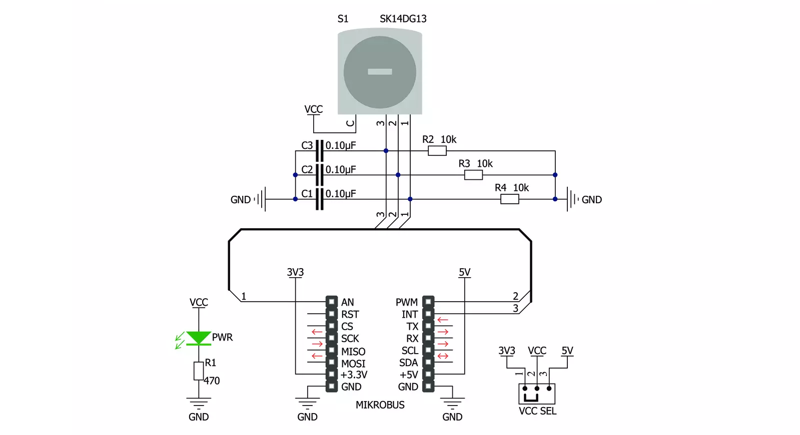
Keylock Click is based on the SK14DG13, a processed sealed key lock mechanism from NKK Switches that can be set in three different positions. The click is designed to run on either a 3.3V or 5V power supply. It communicates with the target microcontroller over the PWM, INT, and AN pin on the mikroBUS™ line. This Click board™
comes with two keys and a protective cap for the mechanism. The contact mechanism provides unequaled logic-level reliability and smoother, positive detent actuation. With its spring-operated steel ball, the detent mechanism gives crisp, positive action for accurate switch settings. This Click board™ can operate with either 3.3V or 5V
logic voltage levels selected via the VCC SEL jumper. This way, both 3.3V and 5V capable MCUs can use the communication lines properly. Also, this Click board™ comes equipped with a library containing easy-to-use functions and an example code that can be used as a reference for further development.


Features overview
Development board
EasyPIC v8 for PIC24/dsPIC33 is a development board specially designed for the needs of rapid development of embedded applications. It supports a wide range of 16-bit PIC24/dsPIC33 microcontrollers from Microchip and has a broad set of unique functions, such as the first-ever embedded debugger/programmer. The development board is well organized and designed so that the end-user has all the necessary elements, such as switches, buttons, indicators, connectors, and others, in one place. Thanks to innovative manufacturing technology, EasyPIC v8 for PIC24/dsPIC33 provides a fluid and immersive working experience, allowing access anywhere and under any circumstances. Each part of the EasyPIC
v8 for PIC24/dsPIC33 development board contains the components necessary for the most efficient operation of the same board. In addition to the advanced integrated CODEGRIP programmer/debugger module, which offers many valuable programming/debugging options and seamless integration with the Mikroe software environment, the board also includes a clean and regulated power supply module for the development board. It can use a wide range of external power sources, including a battery, an external 12V power supply, and a power source via the USB Type-C (USB-C) connector. Communication options such as USB HOST/DEVICE, USB-UART, CAN, and LIN are also
included, including the well-established mikroBUS™ standard, two display options (graphical and character-based LCD), and several different DIP sockets. These sockets cover a wide range of 16-bit PIC24/dsPIC33 MCUs, from the smallest PIC24/dsPIC33 MCUs with only 14 up to 28 pins. EasyPIC v8 for PIC24/dsPIC33 is an integral part of the Mikroe ecosystem for rapid development. Natively supported by Mikroe software tools, it covers many aspects of prototyping and development thanks to a considerable number of different Click boards™ (over a thousand boards), the number of which is growing every day.

Microcontroller Overview
MCU Card / MCU
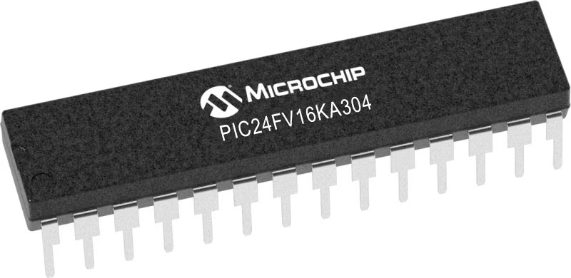
Architecture
dsPIC
MCU Memory (KB)
16
Silicon Vendor
Microchip
Pin count
28
RAM (Bytes)
2048
Used MCU Pins
mikroBUS™ mapper
Take a closer look
Click board™ Schematic
Step by step
Project assembly

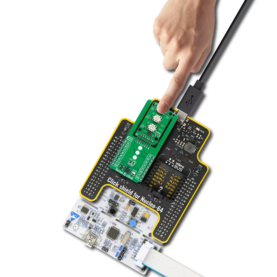
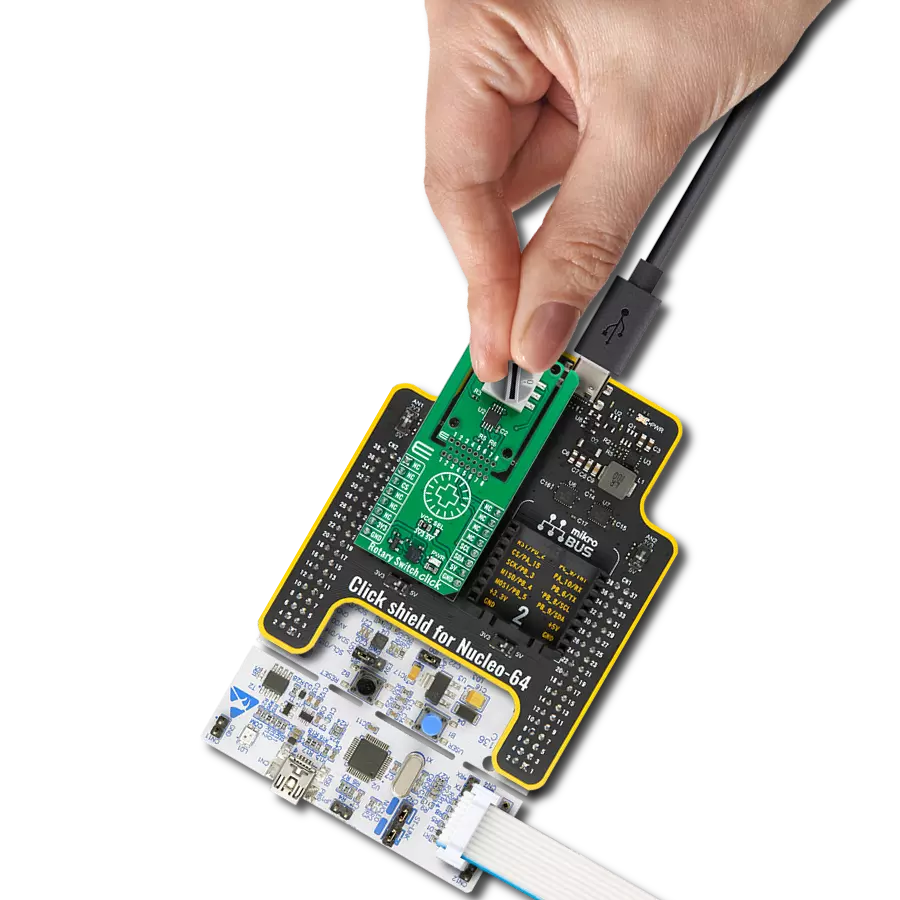
Start by selecting your development board and Click board™. Begin with the EasyPIC v8 for PIC24/dsPIC33 as your development board.


Track your results in real time
Application Output
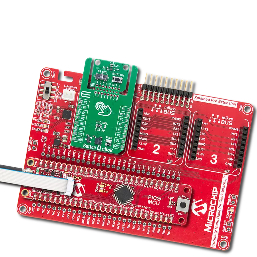
1. Application Output - In Debug mode, the 'Application Output' window enables real-time data monitoring, offering direct insight into execution results. Ensure proper data display by configuring the environment correctly using the provided tutorial.

2. UART Terminal - Use the UART Terminal to monitor data transmission via a USB to UART converter, allowing direct communication between the Click board™ and your development system. Configure the baud rate and other serial settings according to your project's requirements to ensure proper functionality. For step-by-step setup instructions, refer to the provided tutorial.

3. Plot Output - The Plot feature offers a powerful way to visualize real-time sensor data, enabling trend analysis, debugging, and comparison of multiple data points. To set it up correctly, follow the provided tutorial, which includes a step-by-step example of using the Plot feature to display Click board™ readings. To use the Plot feature in your code, use the function: plot(*insert_graph_name*, variable_name);. This is a general format, and it is up to the user to replace 'insert_graph_name' with the actual graph name and 'variable_name' with the parameter to be displayed.

Software Support
Library Description
This library contains API for Keylock Click driver.
Key functions:
keylock_check_pin- Checks pin state.keylock_get_position- Gets key position.
Open Source
Code example
The complete application code and a ready-to-use project are available through the NECTO Studio Package Manager for direct installation in the NECTO Studio. The application code can also be found on the MIKROE GitHub account.
/*!
 * \file
 * \brief Keylock Click example
 *
 * # Description
 * This application monitors key position in its lock mechanism.
 *
 * The demo application is composed of two sections :
 *
 * ## Application Init
 * Initialization driver enables GPIO and also writes log.
 *
 * ## Application Task
 * Detects the position in which the key currently is.
 * Results are being sent to the Terminal, where you can track changes.
 *
 * \author MikroE Team
 *
 */
// ------------------------------------------------------------------- INCLUDES

#include "board.h"
#include "log.h"
#include "keylock.h"

// ------------------------------------------------------------------ VARIABLES

static keylock_t keylock;
static log_t logger;

// ------------------------------------------------------ APPLICATION FUNCTIONS

void application_init ( void )
{
    log_cfg_t log_cfg;
    keylock_cfg_t cfg;

    /**
     * Logger initialization.
     * Default baud rate: 115200
     * Default log level: LOG_LEVEL_DEBUG
     * @note If USB_UART_RX and USB_UART_TX
     * are defined as HAL_PIN_NC, you will
     * need to define them manually for log to work.
     * See @b LOG_MAP_USB_UART macro definition for detailed explanation.
     */
    LOG_MAP_USB_UART( log_cfg );
    log_init( &logger, &log_cfg );
    log_info( &logger, "---- Application Init ----" );

    //  Click initialization.

    keylock_cfg_setup( &cfg );
    KEYLOCK_MAP_MIKROBUS( cfg, MIKROBUS_1 );
    keylock_init( &keylock, &cfg );
    Delay_ms ( 100 );
    log_printf( &logger, "--------------- \r\n" );
    log_printf( &logger, " Keylock Click \r\n" );
    log_printf( &logger, "--------------- \r\n" );
}

void application_task ( void )
{
    uint8_t new_state;
    uint8_t old_state = 0;

    new_state = keylock_get_position( &keylock );

    if ( old_state != new_state )
    {
        if ( new_state == KEYLOCK_KEY_POS_1 )
        {
            log_printf( &logger, " Position ONE \r\n" );
        }
        else if ( new_state == KEYLOCK_KEY_POS_2 )
        {
            log_printf( &logger, " Position TWO \r\n" );
        }
        else if ( new_state == KEYLOCK_KEY_POS_3 )
        {
            log_printf( &logger, " Position THREE \r\n" );
        }
        else
        {
            log_printf( &logger, " ERROR!!! \r\n" );
        }

    old_state = new_state;
    log_printf( &logger, "---------------- \r\n" );
    }

    Delay_ms ( 500 );
}

int main ( void )
{
    /* Do not remove this line or clock might not be set correctly. */
    #ifdef PREINIT_SUPPORTED
    preinit();
    #endif

    application_init( );

    for ( ; ; )
    {
        application_task( );
    }

    return 0;
}

// ------------------------------------------------------------------------ END