Measure motion and acceleration with KX134-1211 and STM32F407VGT6
The dance of data: How accelerometers revolutionize our world

Published Feb 14, 2024
Click board™
Accel 20 Click
Dev. board
Discovery kit with STM32F407VG MCU
Compiler
NECTO Studio
MCU
STM32F407VGT6
This solution makes it possible to enhance safety by monitoring and alerting for sudden movements or impacts
A
A
Hardware Overview
How does it work?
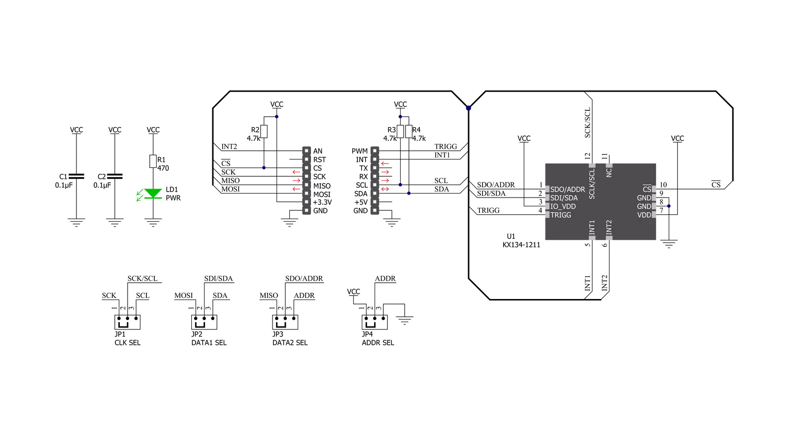
Accel 20 Click is based on the KX134-1211, a highly reliable digital triaxial acceleration sensor with a feature set optimized for machine condition monitoring from Rohm Semiconductor. The KX134-1211 is highly configurable with a programmable acceleration range of ±8/±16/±32/±64g, providing signal conditioning and intelligent user-programmable application algorithms with improved linearity over the entire temperature range. It also has an Advanced Data Path (ADP) technology, which allows noise filtering and sensor signal processing, usually carried out by the MCU, to be performed by the accelerometer. They contribute to reducing MCU load and power consumption and improving application performance. Acceleration sensing is based on the principle of a differential capacitance arising from the acceleration-induced motion of
the sensing element, which is hermetically sealed at the wafer level by bonding a second silicon lid wafer to the device wafer, further utilizing a standard mode cancellation to decrease errors from process variation, temperature, and environmental stress. The KX134-1211 also features an advanced Wake-Up and Back-to-Sleep detection with a high-resolution threshold capability configurable down to 15.6mg, 512-byte buffer that continues to record data even when being read, as well as embedded engines for orientation, directional/double-tap, and free-fall detection. Accel 20 Click allows the use of both I2C and SPI interfaces with a maximum frequency of 3.4MHz for I2C and 10MHz for SPI communication. The selection can be made by positioning SMD jumpers labeled COMM SEL in an appropriate position. Note that all the jumpers' positions must
be on the same side, or the Click board™ may become unresponsive. While the I2C interface is selected, the KX134-1211 allows choosing the least significant bit (LSB) of its I2C slave address using the SMD jumper labeled ADDR SEL. The Accel 20 also possesses two interrupts, I1 and I2, routed to the INT and AN pins on the mikroBUS™ used to signal MCU that an event has been sensed, and one trigger pin labeled as TRG, routed to the PWM pins on the mikroBUS™ socket, used for FIFO buffer control. This Click board™ can be operated only with a 3.3V logic voltage level. The board must perform appropriate logic voltage level conversion before using MCUs with different logic levels. Also, it comes equipped with a library containing functions and an example code that can be used as a reference for further development.


Features overview
Development board
Discovery kit with STM32F407VG MCU, powered by the STM32F407 microcontroller, simplifies audio application development. It offers a robust platform with features like the ST-LINK/V2-A debugger, STMEMS digital accelerometer, digital microphone, and integrated audio DAC with a class D speaker driver. It has LEDs, push buttons, and a USB OTG
Micro-AB connector for versatile connectivity. The STM32F407VGT6 MCU boasts a 32-bit Arm Cortex-M4 with FPU, 1MB Flash memory, and 192KB RAM, housed in an LQFP100 package. Equipped with USB OTG FS, MEMS accelerometer, omnidirectional digital microphone, and user-friendly buttons, it ensures seamless operation.
The board accommodates various add-ons via extension headers while offering flexible power supply options, including ST-LINK, USB VBUS, or external sources. Supported by comprehensive free software and a range of IDEs, it empowers developers with flexibility and ease of use, making it an ideal choice for audio-centric projects.

Microcontroller Overview
MCU Card / MCU

Architecture
ARM Cortex-M4
MCU Memory (KB)
10
Silicon Vendor
STMicroelectronics
Pin count
100
RAM (Bytes)
100
You complete me!
Accessories
STM32F4 Discovery Shield is the perfect extension for your STM32F4 Discovery Board from STMicroelectronics. This versatile shield features four mikroBUS™ host sockets, a USB-UART module, and a CAN transceiver, expanding the capabilities of your Discovery board. Acting as a docking station, the STM32F4 Discovery Shield enables you to effortlessly transform your board into various applications, whether it's an RFID lock, SMS-triggered control switch, GPS tracking device, full-blown weather station, or any other idea you have in mind. With its seamless integration and enhanced functionality, this shield empowers you to explore endless possibilities and quickly bring your projects to life.

Used MCU Pins
mikroBUS™ mapper
Take a closer look
Click board™ Schematic
Step by step
Project assembly

Start by selecting your development board and Click board™. Begin with the Discovery kit with STM32F407VG MCU as your development board.


Software Support
Library Description
This library contains API for Accel 20 Click driver.
Key functions:
accel20_get_axis_data- Accel 20 get accelerometer axis functionaccel20_set_output_data_rate- Accel 20 set output data rate functionaccel20_set_accel_range- Accel 20 set accel range function
Open Source
Code example
The complete application code and a ready-to-use project are available through the NECTO Studio Package Manager for direct installation in the NECTO Studio. The application code can also be found on the MIKROE GitHub account.
/*!
 * @file main.c
 * @brief Accel20 Click example
 *
 * # Description
 * This library contains API for Accel 20 Click driver.
 * The library initializes and defines the I2C or SPI bus drivers
 * to write and read data from registers.
 * The library also includes a function for reading X-axis, Y-axis, and Z-axis data.
 *
 * The demo application is composed of two sections :
 *
 * ## Application Init
 * The initialization of I2C or SPI module, log UART, and additional pins.
 * After the driver init, the app executes a default configuration,
 * checks communication and device ID.
 *
 * ## Application Task
 * This is an example that demonstrates the use of the Accel 20 Click board™.
 * Measures and displays acceleration data for X-axis, Y-axis, and Z-axis.
 * Results are being sent to the USART terminal where the user can track their changes.
 * This task repeats every 1 sec.
 *
 * @author Nenad Filipovic
 *
 */

#include "board.h"
#include "log.h"
#include "accel20.h"

static accel20_t accel20;
static log_t logger;

void application_init ( void )
{
    log_cfg_t log_cfg;          /**< Logger config object. */
    accel20_cfg_t accel20_cfg;  /**< Click config object. */

    /**
     * Logger initialization.
     * Default baud rate: 115200
     * Default log level: LOG_LEVEL_DEBUG
     * @note If USB_UART_RX and USB_UART_TX
     * are defined as HAL_PIN_NC, you will
     * need to define them manually for log to work.
     * See @b LOG_MAP_USB_UART macro definition for detailed explanation.
     */
    LOG_MAP_USB_UART( log_cfg );
    log_init( &logger, &log_cfg );
    log_info( &logger, " Application Init " );

    // Click initialization.
    accel20_cfg_setup( &accel20_cfg );
    ACCEL20_MAP_MIKROBUS( accel20_cfg, MIKROBUS_1 );
    err_t init_flag  = accel20_init( &accel20, &accel20_cfg );
    if ( ( I2C_MASTER_ERROR == init_flag ) || ( SPI_MASTER_ERROR == init_flag ) )
    {
        log_error( &logger, " Application Init Error. " );
        log_info( &logger, " Please, run program again... " );

        for ( ; ; );
    }

    accel20_default_cfg ( &accel20 );
    log_info( &logger, " Application Task " );
    log_printf( &logger, "-------------------------\r\n" );
    log_printf( &logger, "      Accel 20 Click     \r\n" );
    log_printf( &logger, "-------------------------\r\n" );
    Delay_ms ( 100 );

    if ( accel20_check_id( &accel20 ) == ACCEL20_OK )
    {
        log_printf( &logger, "     Communication OK    \r\n" );
        log_printf( &logger, "-------------------------\r\n" );
    }
    else
    {
        log_printf( &logger, "   Communication ERROR   \r\n" );
        log_printf( &logger, "     Reset the device    \r\n" );
        log_printf( &logger, "-------------------------\r\n" );

        for ( ; ; );
    }

    log_printf( &logger, "       Accel Data:       \r\n" );
    log_printf( &logger, "-------------------------\r\n" );
    Delay_ms ( 100 );
}

void application_task ( void )
{
    static accel20_axis_t axis;

    if ( accel20_get_int_1( &accel20 ) == ACCEL20_INT1_DATA_READY )
    {
        accel20_get_axis_data( &accel20, &axis );
        log_printf( &logger, "\tX : %d \r\n\tY : %d \r\n\tZ : %d \r\n", axis.x, axis.y, axis.z );
        log_printf( &logger, "-------------------------\r\n" );
        Delay_ms ( 1000 );
    }
    Delay_ms ( 1 );
}

int main ( void )
{
    /* Do not remove this line or clock might not be set correctly. */
    #ifdef PREINIT_SUPPORTED
    preinit();
    #endif

    application_init( );

    for ( ; ; )
    {
        application_task( );
    }

    return 0;
}

// ------------------------------------------------------------------------ END
Additional Support
Resources
Category:Motion


