Explore unmatched LED performance with MCP1662 and STM32F413ZH
Shine bright, capture attention
Published Feb 14, 2024
Click board™
LED Driver Click
Dev. board
Nucleo 144 with STM32F413ZH MCU
Compiler
NECTO Studio
MCU
STM32F413ZH
Our LED driver solution redefines brilliance, delivering unmatched control, efficiency, and versatility to illuminate your projects with precision
A
A
Hardware Overview
How does it work?
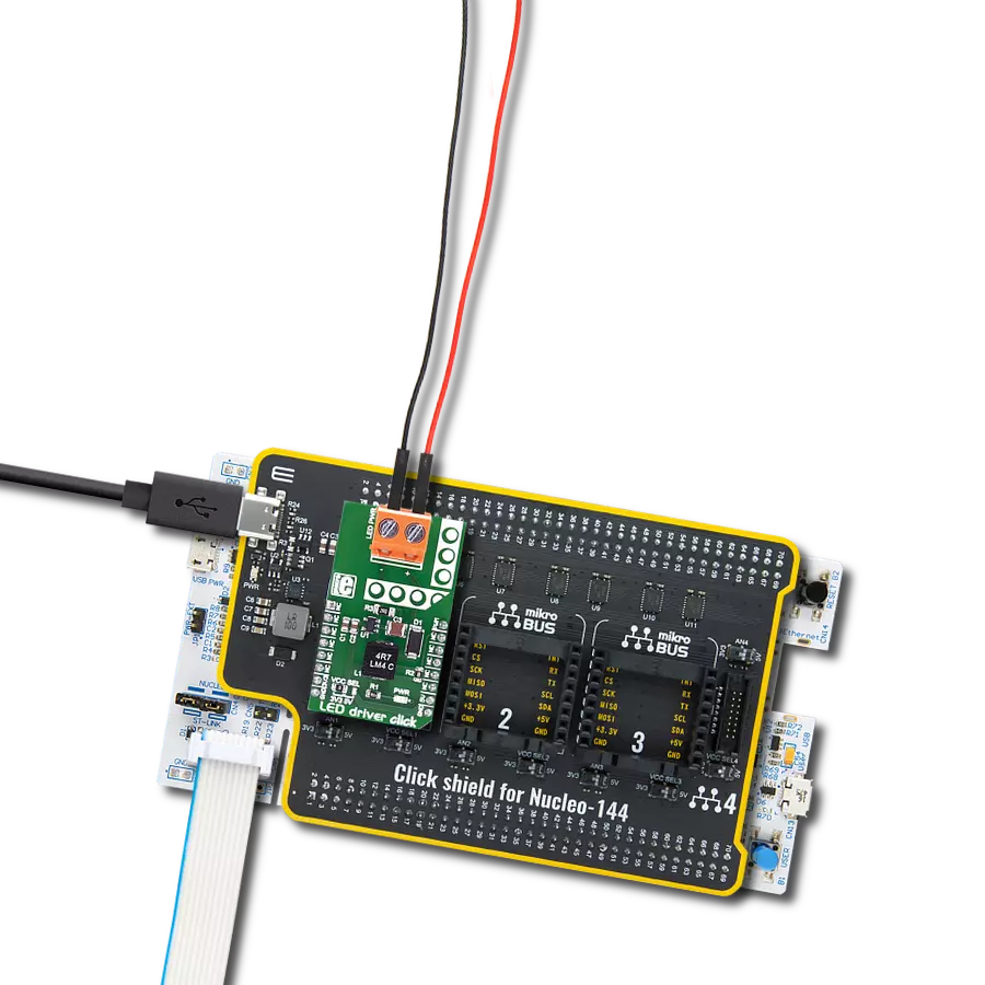
LED Driver Click is based on the MCP1662, a high-voltage step-up voltage driver from Microchip. This Click is designed to run on either a 3.3V or 5V power supply. It communicates with the target microcontroller over the PWM pin on the mikroBUS™ line. The MCP1662 device is a compact, space-efficient, fixed-frequency, non-synchronous step-up converter optimized to drive
LED strings with a constant current from a two- or three-cell alkaline or lithium Energizer® or NiMH/NiCd or one-cell Lithium-Ion or Li-Polymer batteries. The device integrates a 36V, 800 mW low-side switch protected by the 1.3A cycle-by-cycle inductor peak current limit operation. LED driver click has a power input and a PWM input to dim the LED lights. It's an excellent choice for
driving LED strips. This Click board™ can operate with either 3.3V or 5V logic voltage levels selected via the VCC SEL jumper. This way, both 3.3V and 5V capable MCUs can use the communication lines properly. Also, this Click board™ comes equipped with a library containing easy-to-use functions and an example code that can be used as a reference for further development.

Features overview
Development board
Nucleo-144 with STM32F413ZH MCU board offers an accessible and adaptable avenue for users to explore new ideas and construct prototypes. It allows users to tailor their experience by selecting from a range of performance and power consumption features offered by the STM32 microcontroller. With compatible boards, the
internal or external SMPS dramatically decreases power usage in Run mode. Including the ST Zio connector, expanding ARDUINO Uno V3 connectivity, and ST morpho headers facilitate easy expansion of the Nucleo open development platform. The integrated ST-LINK debugger/programmer enhances convenience by
eliminating the need for a separate probe. Moreover, the board is accompanied by comprehensive free software libraries and examples within the STM32Cube MCU Package, further enhancing its utility and value.

Microcontroller Overview
MCU Card / MCU

Architecture
ARM Cortex-M4
MCU Memory (KB)
1536
Silicon Vendor
STMicroelectronics
Pin count
144
RAM (Bytes)
327680
You complete me!
Accessories
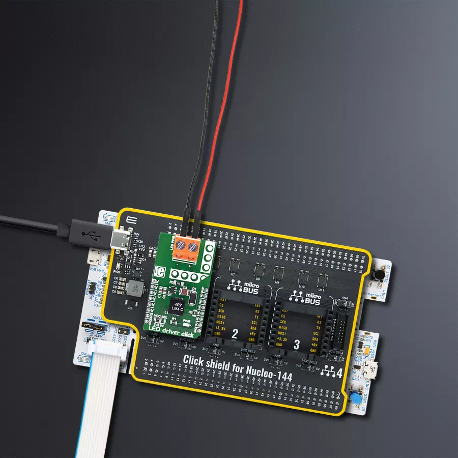
Click Shield for Nucleo-144 comes equipped with four mikroBUS™ sockets, with one in the form of a Shuttle connector, allowing all the Click board™ devices to be interfaced with the STM32 Nucleo-144 board with no effort. This way, MIKROE allows its users to add any functionality from our ever-growing range of Click boards™, such as WiFi, GSM, GPS, Bluetooth, ZigBee, environmental sensors, LEDs, speech recognition, motor control, movement sensors, and many more. Featuring an ARM Cortex-M microcontroller, 144 pins, and Arduino™ compatibility, the STM32 Nucleo-144 board offers limitless possibilities for prototyping and creating diverse applications. These boards are controlled and powered conveniently through a USB connection to program and efficiently debug the Nucleo-144 board out of the box, with an additional USB cable connected to the USB mini port on the board. Simplify your project development with the integrated ST-Link debugger and unleash creativity using the extensive I/O options and expansion capabilities. This Click Shield also has several switches that perform functions such as selecting the logic levels of analog signals on mikroBUS™ sockets and selecting logic voltage levels of the mikroBUS™ sockets themselves. Besides, the user is offered the possibility of using any Click board™ with the help of existing bidirectional level-shifting voltage translators, regardless of whether the Click board™ operates at a 3.3V or 5V logic voltage level. Once you connect the STM32 Nucleo-144 board with our Click Shield for Nucleo-144, you can access hundreds of Click boards™, working with 3.3V or 5V logic voltage levels.

Used MCU Pins
mikroBUS™ mapper
Take a closer look
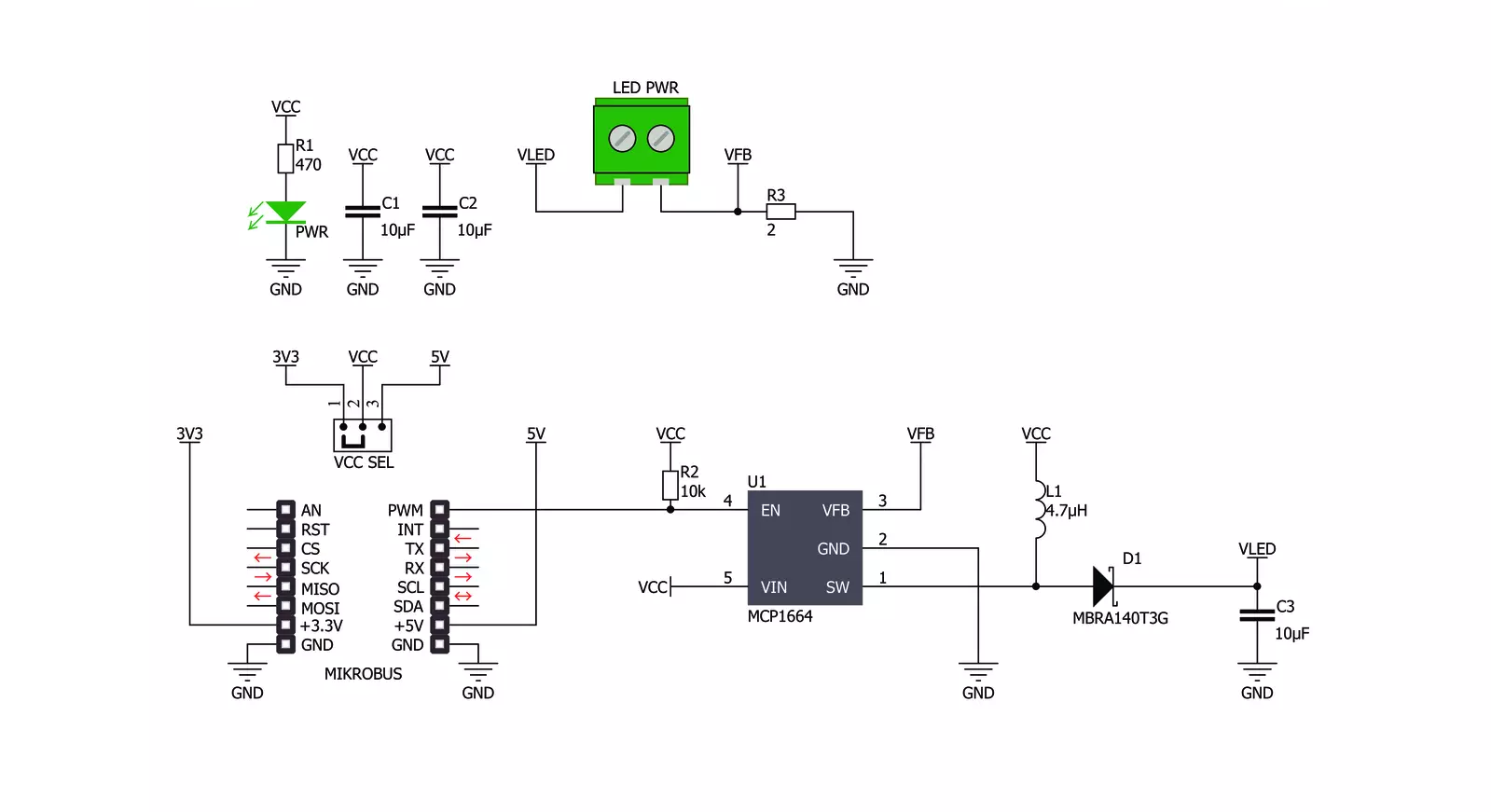
Click board™ Schematic
Step by step
Project assembly
Start by selecting your development board and Click board™. Begin with the Nucleo 144 with STM32F413ZH MCU as your development board.


Track your results in real time
Application Output
1. Application Output - In Debug mode, the 'Application Output' window enables real-time data monitoring, offering direct insight into execution results. Ensure proper data display by configuring the environment correctly using the provided tutorial.

2. UART Terminal - Use the UART Terminal to monitor data transmission via a USB to UART converter, allowing direct communication between the Click board™ and your development system. Configure the baud rate and other serial settings according to your project's requirements to ensure proper functionality. For step-by-step setup instructions, refer to the provided tutorial.

3. Plot Output - The Plot feature offers a powerful way to visualize real-time sensor data, enabling trend analysis, debugging, and comparison of multiple data points. To set it up correctly, follow the provided tutorial, which includes a step-by-step example of using the Plot feature to display Click board™ readings. To use the Plot feature in your code, use the function: plot(*insert_graph_name*, variable_name);. This is a general format, and it is up to the user to replace 'insert_graph_name' with the actual graph name and 'variable_name' with the parameter to be displayed.

Software Support
Library Description
This library contains API for LED Driver Click driver.
Key functions:
leddriver_pwm_start- Start PWMleddriver_pwm_stop- Stop PWM
Open Source
Code example
The complete application code and a ready-to-use project are available through the NECTO Studio Package Manager for direct installation in the NECTO Studio. The application code can also be found on the MIKROE GitHub account.
/*!
 * \file
 * \brief LedDriver Click example
 *
 * # Description
 * This library contains API for the LED Driver Click driver.
 * This application controls the brightness.
 *
 * The demo application is composed of two sections :
 *
 * ## Application Init
 * PWM initialization set PWM duty cycle and PWM frequency and start PWM.
 *
 * ## Application Task
 * This is an example that demonstrates the use of the LED Driver Click board.
 * LED Driver Click communicates with register via PWM interface.
 * This example shows the automatic control halogen bulb light intensity,
 * the first intensity of light is rising and then the intensity of light is falling.
 * Results are being sent to the Usart Terminal where you can track their changes.
 *
 * \author Nikola Peric
 *
 */
// ------------------------------------------------------------------- INCLUDES

#include "board.h"
#include "log.h"
#include "leddriver.h"

// ------------------------------------------------------------------ VARIABLES

static leddriver_t leddriver;
static log_t logger;

void application_init ( void )
{
    log_cfg_t log_cfg;
    leddriver_cfg_t cfg;

    /**
     * Logger initialization.
     * Default baud rate: 115200
     * Default log level: LOG_LEVEL_DEBUG
     * @note If USB_UART_RX and USB_UART_TX
     * are defined as HAL_PIN_NC, you will
     * need to define them manually for log to work.
     * See @b LOG_MAP_USB_UART macro definition for detailed explanation.
     */
    LOG_MAP_USB_UART( log_cfg );
    log_init( &logger, &log_cfg );
    log_info( &logger, "---- Application Init ----" );

    //  Click initialization.

    leddriver_cfg_setup( &cfg );
    LEDDRIVER_MAP_MIKROBUS( cfg, MIKROBUS_1 );

    if ( LEDDRIVER_OK != leddriver_init( &leddriver, &cfg ) )
    {
        log_info( &logger, "---- Init Error ----" );
        log_info( &logger, "---- Run program again ----" );

        for ( ; ; );
    }

    log_info( &logger, "---- Init Done ----\r\n" );
    leddriver_set_duty_cycle ( &leddriver, 0.0 );
    leddriver_pwm_start( &leddriver );
    Delay_ms ( 100 );
    log_info( &logger, "---- Application Task ----\r\n" );
}

void application_task ( void )
{
    static int8_t duty_cnt = 1;
    static int8_t duty_inc = 1;
    float duty = duty_cnt / 10.0;

    leddriver_set_duty_cycle ( &leddriver, duty );
    log_printf( &logger, "> Duty: %d%%\r\n", ( uint16_t )( duty_cnt * 10 ) );

    Delay_ms ( 500 );

    if ( 10 == duty_cnt )
    {
        duty_inc = -1;
    }
    else if ( 0 == duty_cnt )
    {
        duty_inc = 1;
    }
    duty_cnt += duty_inc;
}

int main ( void )
{
    /* Do not remove this line or clock might not be set correctly. */
    #ifdef PREINIT_SUPPORTED
    preinit();
    #endif

    application_init( );

    for ( ; ; )
    {
        application_task( );
    }

    return 0;
}


// ------------------------------------------------------------------------ END


