Make accurate digital representation of analog signals with ADC121S021 and STM32F410RB
Embrace the digital age

Published Oct 08, 2024
Click board™
ADC 5 click
Dev. board
Nucleo 64 with STM32F410RB MCU
Compiler
NECTO Studio
MCU
STM32F410RB
Don't settle for less than the best – choose our ADC for your next project!
A
A
Hardware Overview
How does it work?
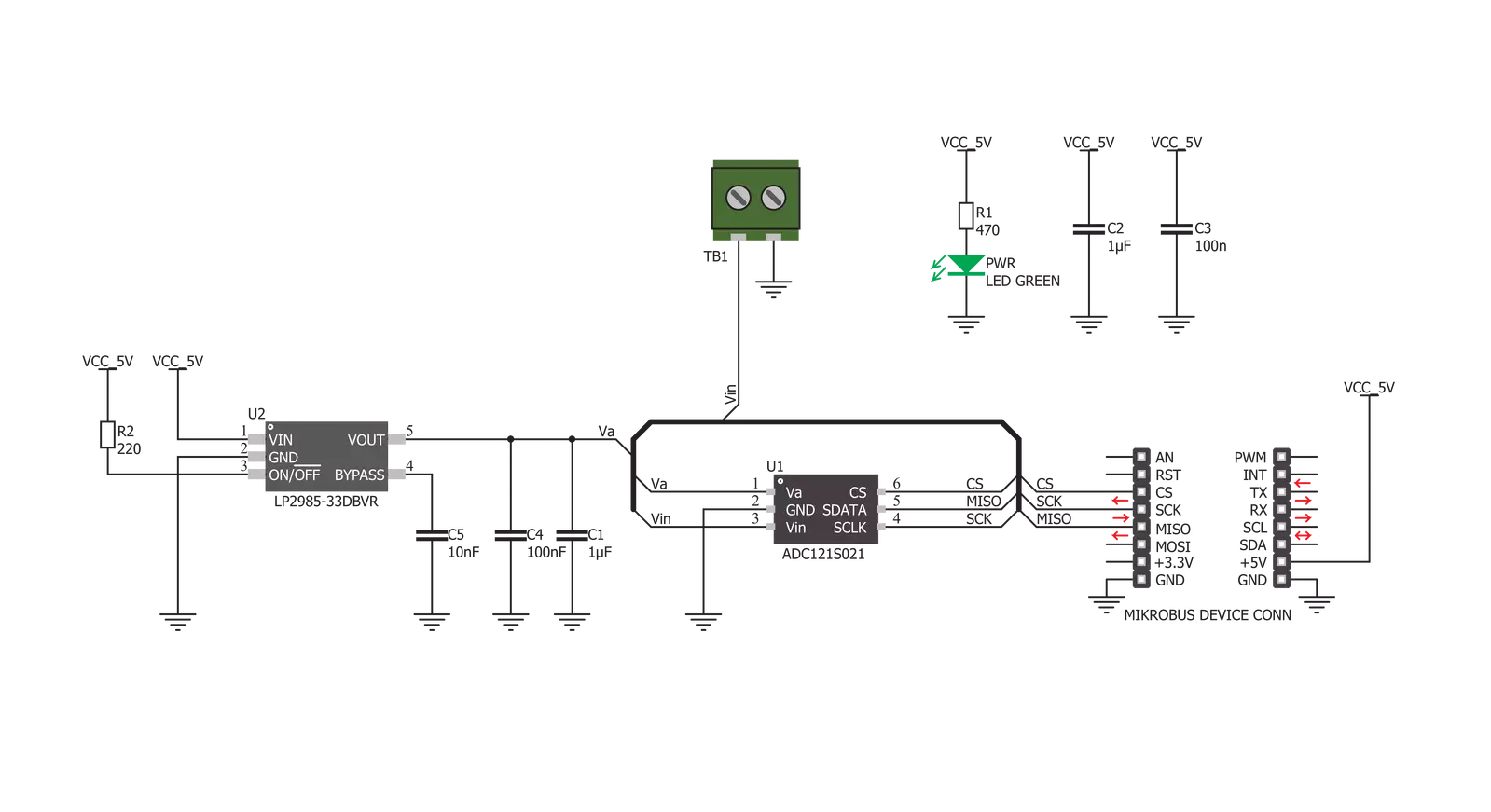
ADC 5 Click is based on the ADC121S021, a 12-bit CMOS ADC device from Texas Instruments. This AD converter uses a reference voltage obtained from the LP2985 LDO regulator from the same company. It provides a clean and accurate regulated voltage on its output, perfectly suited to this converter's reference voltage. Since the reference voltage is set to 3.3V, the maximum value of the input voltage is also 3.3V. The device uses SPI communication. The MOSI pin does not exist since no communication from the MCU to the click board™ is going on. The reading speed, also known as the sample rate, directly depends on the clock rate of the SCK line. The sample rate over which the specified electrical performance is ensured is 50 Ks/s to 200 Ks/s. The ADC121S021 can use any clock signal frequency up to the rated maximum frequency, with
no significant deviations from the specifications stated in the datasheet: it is specified over a wide range of sample rates, maintaining good linearity and high signal-to-noise ratio (SNR). ADC (analog to digital converters) are the most commonly used devices for converting voltage signals into information, which can then be processed in the digital domain. There are many types of ADC converters commercially available. They can vary in bit depth, sample rate, approximation algorithm (SAR or delta-sigma), and more. Those attributes affect how accurately the sampled voltage will be translated into the digital world. The sample rate is usually the determining factor when the maximum frequency of the input signal is considered. The aliasing of the input signal can occur as the input signal frequency is nearing half the sample rate
of the converter. This frequency limits the bandwidth of the input signal, also called the Nyquist frequency, so using input frequencies near or above the Nyquist frequency results in an inaccurate conversion. The ADC121S021 converter uses the SAR, or the successive approximation method, for the conversion, which compares the input voltage with a series of internally generated voltage values. The approximation is stored in a successive approximation register at each step in this process. The comparing steps are continued until the desired resolution is reached. The ADC click board is also equipped with a screw terminal, which can be used for easy and secure connection of the input voltage rail. Although the reference voltage is 3.3V, it is powered only by the 5V rail from the mikroBUS™, used as the input for the LDO regulator.

Features overview
Development board
Nucleo-64 with STM32F410RB MCU offers a cost-effective and adaptable platform for developers to explore new ideas and prototype their designs. This board harnesses the versatility of the STM32 microcontroller, enabling users to select the optimal balance of performance and power consumption for their projects. It accommodates the STM32 microcontroller in the LQFP64 package and includes essential components such as a user LED, which doubles as an ARDUINO® signal, alongside user and reset push-buttons, and a 32.768kHz crystal oscillator for precise timing operations. Designed with expansion and flexibility in mind, the Nucleo-64 board features an ARDUINO® Uno V3 expansion connector and ST morpho extension pin
headers, granting complete access to the STM32's I/Os for comprehensive project integration. Power supply options are adaptable, supporting ST-LINK USB VBUS or external power sources, ensuring adaptability in various development environments. The board also has an on-board ST-LINK debugger/programmer with USB re-enumeration capability, simplifying the programming and debugging process. Moreover, the board is designed to simplify advanced development with its external SMPS for efficient Vcore logic supply, support for USB Device full speed or USB SNK/UFP full speed, and built-in cryptographic features, enhancing both the power efficiency and security of projects. Additional connectivity is
provided through dedicated connectors for external SMPS experimentation, a USB connector for the ST-LINK, and a MIPI® debug connector, expanding the possibilities for hardware interfacing and experimentation. Developers will find extensive support through comprehensive free software libraries and examples, courtesy of the STM32Cube MCU Package. This, combined with compatibility with a wide array of Integrated Development Environments (IDEs), including IAR Embedded Workbench®, MDK-ARM, and STM32CubeIDE, ensures a smooth and efficient development experience, allowing users to fully leverage the capabilities of the Nucleo-64 board in their projects.

Microcontroller Overview
MCU Card / MCU

Architecture
ARM Cortex-M4
MCU Memory (KB)
128
Silicon Vendor
STMicroelectronics
Pin count
64
RAM (Bytes)
32768
You complete me!
Accessories
Click Shield for Nucleo-64 comes equipped with two proprietary mikroBUS™ sockets, allowing all the Click board™ devices to be interfaced with the STM32 Nucleo-64 board with no effort. This way, Mikroe allows its users to add any functionality from our ever-growing range of Click boards™, such as WiFi, GSM, GPS, Bluetooth, ZigBee, environmental sensors, LEDs, speech recognition, motor control, movement sensors, and many more. More than 1537 Click boards™, which can be stacked and integrated, are at your disposal. The STM32 Nucleo-64 boards are based on the microcontrollers in 64-pin packages, a 32-bit MCU with an ARM Cortex M4 processor operating at 84MHz, 512Kb Flash, and 96KB SRAM, divided into two regions where the top section represents the ST-Link/V2 debugger and programmer while the bottom section of the board is an actual development board. These boards are controlled and powered conveniently through a USB connection to program and efficiently debug the Nucleo-64 board out of the box, with an additional USB cable connected to the USB mini port on the board. Most of the STM32 microcontroller pins are brought to the IO pins on the left and right edge of the board, which are then connected to two existing mikroBUS™ sockets. This Click Shield also has several switches that perform functions such as selecting the logic levels of analog signals on mikroBUS™ sockets and selecting logic voltage levels of the mikroBUS™ sockets themselves. Besides, the user is offered the possibility of using any Click board™ with the help of existing bidirectional level-shifting voltage translators, regardless of whether the Click board™ operates at a 3.3V or 5V logic voltage level. Once you connect the STM32 Nucleo-64 board with our Click Shield for Nucleo-64, you can access hundreds of Click boards™, working with 3.3V or 5V logic voltage levels.

Used MCU Pins
mikroBUS™ mapper
Take a closer look
Click board™ Schematic
Step by step
Project assembly
Start by selecting your development board and Click board™. Begin with the Nucleo 64 with STM32F410RB MCU as your development board.


Track your results in real time
Application Output
1. Application Output - In Debug mode, the 'Application Output' window enables real-time data monitoring, offering direct insight into execution results. Ensure proper data display by configuring the environment correctly using the provided tutorial.

2. UART Terminal - Use the UART Terminal to monitor data transmission via a USB to UART converter, allowing direct communication between the Click board™ and your development system. Configure the baud rate and other serial settings according to your project's requirements to ensure proper functionality. For step-by-step setup instructions, refer to the provided tutorial.

3. Plot Output - The Plot feature offers a powerful way to visualize real-time sensor data, enabling trend analysis, debugging, and comparison of multiple data points. To set it up correctly, follow the provided tutorial, which includes a step-by-step example of using the Plot feature to display Click board™ readings. To use the Plot feature in your code, use the function: plot(*insert_graph_name*, variable_name);. This is a general format, and it is up to the user to replace 'insert_graph_name' with the actual graph name and 'variable_name' with the parameter to be displayed.

Software Support
Library Description
This library contains API for ADC 5 Click driver.
Key functions:
adc5_getData - This function returns raw 10-bit data
adc5_getVoltage - This function returns measured voltage in millivolts
Open Source
Code example
The complete application code and a ready-to-use project are available through the NECTO Studio Package Manager for direct installation in the NECTO Studio. The application code can also be found on the MIKROE GitHub account.
/*!
 * \file
 * \brief ADC5 Click example
 *
 * # Description
 * This example showcases how to initialize and configure the logger and Click modules and
 * how to read and display ADC voltage data from the Click.
 *
 * The demo application is composed of two sections :
 *
 * ## Application Init
 * This function initializes and configures the logger and Click modules.
 *
 * ## Application Task
 * This function reads and displays ADC voltage data every second.
 *
 * \author MikroE Team
 *
 */
// ------------------------------------------------------------------- INCLUDES

#include "board.h"
#include "log.h"
#include "adc5.h"

// ------------------------------------------------------------------ VARIABLES

static adc5_t adc5;
static log_t logger;

// ------------------------------------------------------ APPLICATION FUNCTIONS

void application_init ( )
{
    log_cfg_t log_cfg;
    adc5_cfg_t cfg;

    /**
     * Logger initialization.
     * Default baud rate: 115200
     * Default log level: LOG_LEVEL_DEBUG
     * @note If USB_UART_RX and USB_UART_TX
     * are defined as HAL_PIN_NC, you will
     * need to define them manually for log to work.
     * See @b LOG_MAP_USB_UART macro definition for detailed explanation.
     */
    LOG_MAP_USB_UART( log_cfg );
    log_init( &logger, &log_cfg );
    log_info( &logger, "---- Application Init ----" );
    Delay_ms ( 100 );

    //  Click initialization.

    adc5_cfg_setup( &cfg );
    ADC5_MAP_MIKROBUS( cfg, MIKROBUS_1 );
    adc5_init( &adc5, &cfg );
}

void application_task ( )
{
    uint16_t adc_value;

    adc_value = adc5_get_voltage( &adc5 );
    log_printf( &logger, " * Voltage: %d mV * \r\n", adc_value );
    Delay_1sec( );
}

int main ( void )
{
    /* Do not remove this line or clock might not be set correctly. */
    #ifdef PREINIT_SUPPORTED
    preinit();
    #endif

    application_init( );

    for ( ; ; )
    {
        application_task( );
    }

    return 0;
}

// ------------------------------------------------------------------------ END