Build the next generation of connected devices with DA14531MOD and STM32F103RB
Unleash IoT innovation with SmartBond TINY

Published Oct 08, 2024
Click board™
BLE TINY click
Dev. board
Nucleo 64 with STM32F103RB MCU
Compiler
NECTO Studio
MCU
STM32F103RB
Integrate BLE functionality into IoT systems seamlessly and create advanced connected devices, targeting the forefront of the connected consumer, medical, smart home, and appliance applications
A
A
Hardware Overview
How does it work?
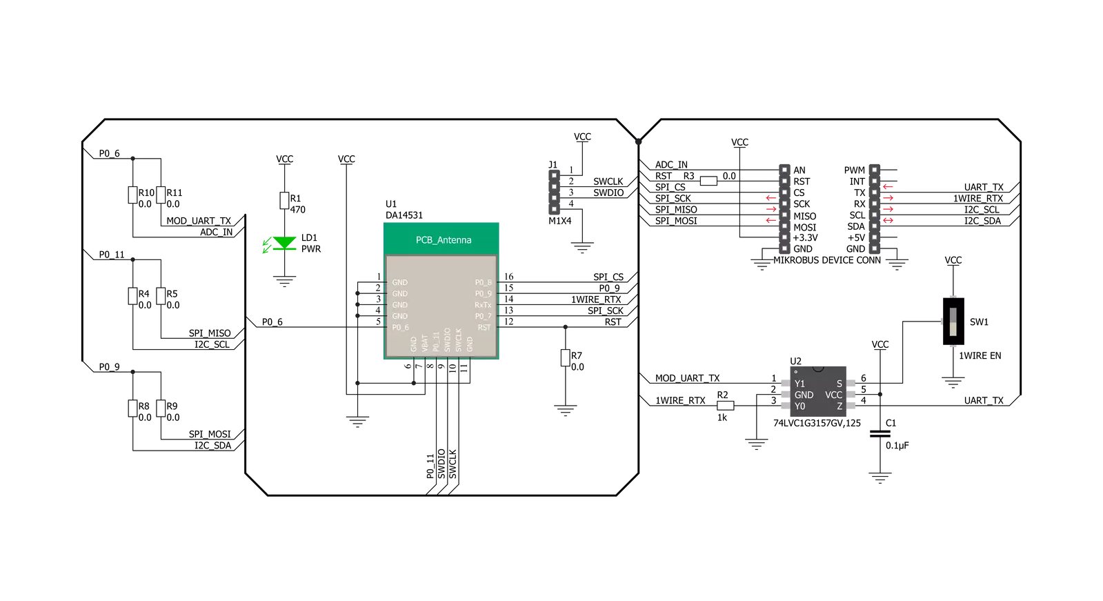
BLE TINY Click is based on the DA14531MOD, SmartBond TINY™ module based on the world's smallest and lowest power Bluetooth 5.1 System-on-Chip (SoC) from Dialog Semiconductor. The DA14531 is based on the powerful 32-bit Arm Cortex-M0+ with integrated memories and analog and digital peripherals. It comes with next-generation Codeless software that allows the design of Bluetooth applications without Bluetooth knowledge or advanced programming skills, using a comprehensive set of AT commands. This module is supported with software to lower the threshold of using BLE technology. The DA14531 has configurable DSPS (serial port service) and next-generation Codeless software to design Bluetooth applications without Bluetooth knowledge or advanced programming skills. It is specifically optimized to significantly reduce the cost of adding Bluetooth low-energy functionality to an IoT system. The SmartBond TINY module is certified worldwide, with Federal Communications
Commission (FCC) certification for the Americas and CE certification for Europe. BLE TINY Click communicates with MCU using the Single-Wire UART interface as its default communication protocol for exchanging AT commands with the host and data transfer. A switch labeled as 1WIRE EN is used to activate this communication, which allows the module to establish communication via the Single-Wire UART Receive and Transmit pin or only via the standard UART TX pin. This Click board™ uses the 74LVC1G3157 multiplexer to avoid conflict with other functions driven by the same GPIOs. In this way, the user can use the P0_6 pin, which carries a dual function, a UART TX pin or a pin to be used for the ADC's analog pin. The function of this pin is selected by populating the appropriate jumper labeled as P0_6 SEL. The DA14531 comes in with a predefined default configuration. However, due to the low GPIO pin count, several functions are multiplexed and can be enabled as needed through onboard jumpers.
The users can also use other interfaces, such as SPI or I2C, to configure the module and write the library by themselves by populating the appropriate jumpers (P0_11 and P0_9 SEL). BLE TINY Click also provides a JTAG interface with SWDIO data and SWCLK clock signals on header J1. This way, the user can program a particular version of the CodeLess software via the JTAG interface, which is required by the DA14531 module itself. Also, this Click board™ can be reset through the Hardware Reset pin, labeled as RST on the mikroBUS™ socket, by setting this pin to a high logic state. This Click board™ can be operated only with a 3.3V logic voltage level. The board must perform appropriate logic voltage level conversion before using MCUs with different logic levels. Also, it comes equipped with a library containing functions and an example code that can be used, as a reference, for further development.

Features overview
Development board
Nucleo-64 with STM32F103RB MCU offers a cost-effective and adaptable platform for developers to explore new ideas and prototype their designs. This board harnesses the versatility of the STM32 microcontroller, enabling users to select the optimal balance of performance and power consumption for their projects. It accommodates the STM32 microcontroller in the LQFP64 package and includes essential components such as a user LED, which doubles as an ARDUINO® signal, alongside user and reset push-buttons, and a 32.768kHz crystal oscillator for precise timing operations. Designed with expansion and flexibility in mind, the Nucleo-64 board features an ARDUINO® Uno V3 expansion connector and ST morpho extension pin
headers, granting complete access to the STM32's I/Os for comprehensive project integration. Power supply options are adaptable, supporting ST-LINK USB VBUS or external power sources, ensuring adaptability in various development environments. The board also has an on-board ST-LINK debugger/programmer with USB re-enumeration capability, simplifying the programming and debugging process. Moreover, the board is designed to simplify advanced development with its external SMPS for efficient Vcore logic supply, support for USB Device full speed or USB SNK/UFP full speed, and built-in cryptographic features, enhancing both the power efficiency and security of projects. Additional connectivity is
provided through dedicated connectors for external SMPS experimentation, a USB connector for the ST-LINK, and a MIPI® debug connector, expanding the possibilities for hardware interfacing and experimentation. Developers will find extensive support through comprehensive free software libraries and examples, courtesy of the STM32Cube MCU Package. This, combined with compatibility with a wide array of Integrated Development Environments (IDEs), including IAR Embedded Workbench®, MDK-ARM, and STM32CubeIDE, ensures a smooth and efficient development experience, allowing users to fully leverage the capabilities of the Nucleo-64 board in their projects.

Microcontroller Overview
MCU Card / MCU

Architecture
ARM Cortex-M3
MCU Memory (KB)
128
Silicon Vendor
STMicroelectronics
Pin count
64
RAM (Bytes)
20480
You complete me!
Accessories
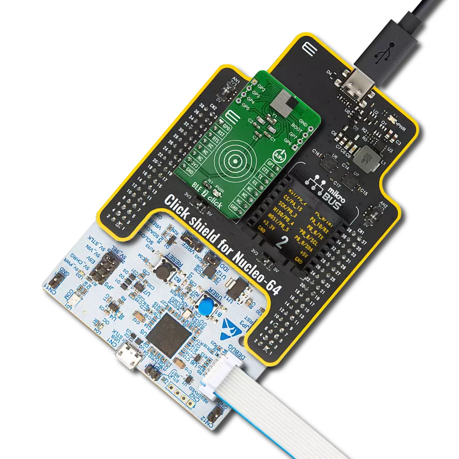
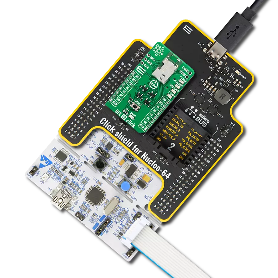
Click Shield for Nucleo-64 comes equipped with two proprietary mikroBUS™ sockets, allowing all the Click board™ devices to be interfaced with the STM32 Nucleo-64 board with no effort. This way, Mikroe allows its users to add any functionality from our ever-growing range of Click boards™, such as WiFi, GSM, GPS, Bluetooth, ZigBee, environmental sensors, LEDs, speech recognition, motor control, movement sensors, and many more. More than 1537 Click boards™, which can be stacked and integrated, are at your disposal. The STM32 Nucleo-64 boards are based on the microcontrollers in 64-pin packages, a 32-bit MCU with an ARM Cortex M4 processor operating at 84MHz, 512Kb Flash, and 96KB SRAM, divided into two regions where the top section represents the ST-Link/V2 debugger and programmer while the bottom section of the board is an actual development board. These boards are controlled and powered conveniently through a USB connection to program and efficiently debug the Nucleo-64 board out of the box, with an additional USB cable connected to the USB mini port on the board. Most of the STM32 microcontroller pins are brought to the IO pins on the left and right edge of the board, which are then connected to two existing mikroBUS™ sockets. This Click Shield also has several switches that perform functions such as selecting the logic levels of analog signals on mikroBUS™ sockets and selecting logic voltage levels of the mikroBUS™ sockets themselves. Besides, the user is offered the possibility of using any Click board™ with the help of existing bidirectional level-shifting voltage translators, regardless of whether the Click board™ operates at a 3.3V or 5V logic voltage level. Once you connect the STM32 Nucleo-64 board with our Click Shield for Nucleo-64, you can access hundreds of Click boards™, working with 3.3V or 5V logic voltage levels.

Used MCU Pins
mikroBUS™ mapper
Take a closer look
Click board™ Schematic
Step by step
Project assembly
Start by selecting your development board and Click board™. Begin with the Nucleo 64 with STM32F103RB MCU as your development board.


Track your results in real time
Application Output
1. Application Output - In Debug mode, the 'Application Output' window enables real-time data monitoring, offering direct insight into execution results. Ensure proper data display by configuring the environment correctly using the provided tutorial.

2. UART Terminal - Use the UART Terminal to monitor data transmission via a USB to UART converter, allowing direct communication between the Click board™ and your development system. Configure the baud rate and other serial settings according to your project's requirements to ensure proper functionality. For step-by-step setup instructions, refer to the provided tutorial.

3. Plot Output - The Plot feature offers a powerful way to visualize real-time sensor data, enabling trend analysis, debugging, and comparison of multiple data points. To set it up correctly, follow the provided tutorial, which includes a step-by-step example of using the Plot feature to display Click board™ readings. To use the Plot feature in your code, use the function: plot(*insert_graph_name*, variable_name);. This is a general format, and it is up to the user to replace 'insert_graph_name' with the actual graph name and 'variable_name' with the parameter to be displayed.

Software Support
Library Description
This library contains API for BLE TINY Click driver.
Key functions:
bletiny_send_cmd- Send command functionbletiny_i2c_config- Configure Click board for I2C master communicationbletiny_i2c_write- Send command to write data to reg address of slave device via I2C communication
Open Source
Code example
The complete application code and a ready-to-use project are available through the NECTO Studio Package Manager for direct installation in the NECTO Studio. The application code can also be found on the MIKROE GitHub account.
/*!
 * @file main.c
 * @brief BLE TINY Click Example.
 *
 * # Description
 * This example reads and processes data from BLE TINY Clicks.
 * Application waits for connection with Click board with phone.
 * Then checks its Coadless FW version and checks connected device.
 * Then waits for command to be stored in it's memory on 0 slot.
 * After that depending on the command stored it executes that type of example.
 *
 * The demo application is composed of two sections :
 *
 * ## Application Init
 * Initializes driver and resets device and seds Disconnect and Reset IO commands.
 * Then it waits for the connection to device. When connected it sends commands to
 * check Coadless FW, connected device, its BLE address and signal quality of
 * connection. In the end it waits for command from its memory. After valid
 * command is stored in memory on 0 slot it contines to Application Task.
 *
 * ## Application Task
 * Executes one of thre application task selected in Application Init:I2C, SPI, APP.
 * I2C example uses EEPROM Click board to write and read data of its memory.
 * SPI example uses EEPROM 2 Click board to write and read data of its memory.
 * APP example just reads UART data and logs it to UART Terminal.
 *
 * ## Additional Function
 * - static void bletiny_clear_app_buf ( void )
 * - static err_t bletiny_process ( void )
 * - static void bletiny_error_check( err_t error_flag );
 * - static void bletiny_log_app_buf ( void );
 * - static err_t bletiny_rsp_check ( void );
 * - static void bletiny_example_init ( void );
 * - static void bletiny_application_example ( void );
 * - static void bletiny_i2c_example ( void );
 * - static void bletiny_spi_example ( void );
 *
 * @note
 * For this application you need to install Dialog's mobile application SmartConsole.
 * This application I2C example is created using EEPROM Click board, and for SPI
 * example EEPROM 2 Click board is used.
 *
 * @author Luka Filipovic
 *
 */

#include "board.h"
#include "log.h"
#include "bletiny.h"
#include "conversions.h"

/**
 * @brief Application receiver buffer size
 * @details Specified size of application receiver buffer.
 */
#define PROCESS_BUFFER_SIZE 200

/**
 * @brief Application example type.
 * @details Specified application example type.
 */
typedef enum
{
    BLETINY_APP_CTRL,
    BLETINY_I2C_EXAMPLE,
    BLETINY_SPI_EXAMPLE
}bletiny_example_type_t;

/**
 * @brief Application example state.
 * @details Specified application example state.
 */
typedef enum
{
    BLETINY_CONFIGURE_MASTER,
    BLETINY_CONFIGURE_SLAVE,
    BLETINY_EXAMPLE
}bletiny_example_state_t;

static bletiny_t bletiny;
static log_t logger;

/**
 * @brief Application @b app_buf and its @b app_buf_cnt and @b app_buf_len.
 * @details Application receiver buffer and its counter and current length.
 */
static char app_buf[ PROCESS_BUFFER_SIZE ] = { 0 };
static int32_t app_buf_len = 0;
static int32_t app_buf_cnt = 0;

/**
 * @brief Application example type and state.
 * @details Application example type and state variables.
 */
static bletiny_example_type_t example_type;
static bletiny_example_state_t example_state;

/**
 * @brief Clearing application buffer.
 * @details This function clears memory of application buffer and reset it's length and counter.
 */
static void bletiny_clear_app_buf ( void );

/**
 * @brief Data reading function.
 * @details This function reads data from device and concatenates data to application buffer.
 *
 * @return @li @c  0 - Read some data.
 *         @li @c -1 - Nothing is read.
 *         @li @c -2 - Application buffer overflow.
 *
 * See #err_t definition for detailed explanation.
 */
static err_t bletiny_process ( void );

/**
 * @brief Parse errors.
 * @details This function checks for different types of errors and logs them on UART.
 */
static void bletiny_error_check( err_t error_flag );

/**
 * @brief Logs application buffer.
 * @details This function logs data from application buffer.
 */
static void bletiny_log_app_buf ( void );

/**
 * @brief Response check.
 * @details This function checks for response and returns the status of response.
 *
 * @return @li @c  >=0 - Success,
 *         @li @c   <0 - Error.
 *
 * See #err_t definition for detailed explanation.
 */
static err_t bletiny_rsp_check ( void );

/**
 * @brief Selecting application task.
 * @details This function selects application task that will be executed.
 * @note Select task by sending command for sending string in memory(0 slot)
 * with phone application. Example of command: AT+MEM=0,I2C. If memory is
 * not empty the string detected will be shown on UART Terminal.
 */
static void bletiny_example_init ( void );

/**
 * @brief Application example.
 * @details This function executes task for using phone application.
 * @note Example logs if any data is read from Click board. This example
 * should be selected if you want to control device with phone application.
 */
static void bletiny_application_example ( void );

/**
 * @brief I2C example.
 * @details This function executes task for using EEPROM Click board.
 * @note Example configures IO pins for I2C communication and configures I2C.
 * Then writes "MikroE" to memory of EEPROM Click board and then reads it
 * back and logs it to UART Terminal.
 */
static void bletiny_i2c_example ( void );

/**
 * @brief SPI example.
 * @details This function executes task for using EEPROM 2 Click board.
 * @note Example configures IO pins for SPI communication and configures SPI.
 * When configured, it sends command for enableing write to Click board memory.
 * Then writes "MikroE" to memory of EEPROM 2 Click board and then reads it
 * back and logs it to UART Terminal.
 */
static void bletiny_spi_example ( void );

/**
 * @brief Clear every @b chr from @b str.
 * @details This function clears every occurance of @b chr from @b str.
 */
static void bletiny_clear_char( uint8_t *str, char chr );

void application_init ( void )
{
    log_cfg_t log_cfg;  /**< Logger config object. */
    bletiny_cfg_t bletiny_cfg;  /**< Click config object. */

    /**
     * Logger initialization.
     * Default baud rate: 115200
     * Default log level: LOG_LEVEL_DEBUG
     * @note If USB_UART_RX and USB_UART_TX
     * are defined as HAL_PIN_NC, you will
     * need to define them manually for log to work.
     * See @b LOG_MAP_USB_UART macro definition for detailed explanation.
     */
    LOG_MAP_USB_UART( log_cfg );
    log_init( &logger, &log_cfg );
    log_printf( &logger, "\r\nApplication Init\r\n" );
    Delay_ms ( 1000 );

    // Click initialization.
    bletiny_cfg_setup( &bletiny_cfg );
    BLETINY_MAP_MIKROBUS( bletiny_cfg, MIKROBUS_1 );
    err_t init_flag  = bletiny_init( &bletiny, &bletiny_cfg );

    if ( init_flag == UART_ERROR )
    {
        log_error( &logger, " Application Init Error. " );
        log_info( &logger, " Please, run program again... " );

        for ( ; ; );
    }
    bletiny_default_cfg ( &bletiny );

    bletiny_send_cmd( &bletiny, BLETINY_CMD_ATR );
    bletiny_send_cmd( &bletiny, BLETINY_CMD_ATZ );
    bletiny_send_cmd( &bletiny, BLETINY_CMD_GAPDISCONNECT );
    bletiny_process( );
    bletiny_clear_app_buf( );

    app_buf_len = 0;
    app_buf_cnt = 0;

    //wait for connection
    log_printf( &logger, " Waiting for phone to connect\r\n" );
    while ( 0 == strstr( app_buf, BLETINY_CONNECTED ) )
    {
        bletiny_process( );
    }
    log_printf( &logger, " Connected\r\n" );
    bletiny_clear_app_buf( );
    //send ATI command to check Codless FW
    bletiny_send_cmd( &bletiny, BLETINY_CMD_ATI );
    volatile err_t app_error_flag = bletiny_rsp_check();
    if ( BLETINY_OK == app_error_flag )
    {
        bletiny_log_app_buf();
        log_printf( &logger, "-----------------------------------\r\n" );
    }
    else
    {
        bletiny_error_check( app_error_flag );
    }
    Delay_ms ( 1000 );
    //send command to check ble address
    bletiny_send_cmd( &bletiny, BLETINY_CMD_BDADDR );
    app_error_flag = bletiny_rsp_check();
    if ( BLETINY_OK == app_error_flag )
    {
        bletiny_log_app_buf();
        log_printf( &logger, "-----------------------------------\r\n" );
    }
    else
    {
        bletiny_error_check( app_error_flag );
    }
    Delay_ms ( 1000 );
    //send ATrI command to check remote connected device
    bletiny_send_cmd( &bletiny, BLETINY_CMD_ATRI );
    app_error_flag = bletiny_rsp_check();
    if ( BLETINY_OK == app_error_flag )
    {
        bletiny_log_app_buf();
        log_printf( &logger, "-----------------------------------\r\n" );
    }
    else
    {
        bletiny_error_check( app_error_flag );
    }
    Delay_ms ( 1000 );
    //send RSSI command to check signal quality
    bletiny_send_cmd( &bletiny, BLETINY_CMD_RSSI );
    app_error_flag = bletiny_rsp_check();
    if ( BLETINY_OK == app_error_flag )
    {
        bletiny_log_app_buf();
        log_printf( &logger, "-----------------------------------\r\n" );
    }
    else
    {
        bletiny_error_check( app_error_flag );
    }
    //select example to execute
    bletiny_example_init( );

    bletiny_clear_app_buf( );
    log_printf( &logger, " Application Task \r\n" );
}

void application_task ( void )
{
    static uint8_t info = 0;
    switch ( example_type )
    {
        case BLETINY_I2C_EXAMPLE:
        {
            if (!info)
            {
                info++;
                log_printf( &logger, " I2C example\r\n" );
                bletiny_process( );
                bletiny_clear_app_buf( );
            }
            bletiny_i2c_example( );
            break;
        }
        case BLETINY_SPI_EXAMPLE:
        {
            if (!info)
            {
                info++;
                log_printf( &logger, " SPI example\r\n" );
                bletiny_process( );
                bletiny_clear_app_buf( );
            }
            bletiny_spi_example( );
            break;
        }
        case BLETINY_APP_CTRL:
        {
            if (!info)
            {
                info++;
                log_printf( &logger, " Application example\r\n" );
                bletiny_process( );
                bletiny_clear_app_buf( );
            }
            bletiny_application_example( );
            break;
        }
        default:
        {
            break;
        }
    }
}

int main ( void )
{
    /* Do not remove this line or clock might not be set correctly. */
    #ifdef PREINIT_SUPPORTED
    preinit();
    #endif

    application_init( );

    for ( ; ; )
    {
        application_task( );
    }

    return 0;
}

static void bletiny_clear_app_buf ( void )
{
    memset( app_buf, 0, app_buf_len );
    app_buf_len = 0;
    app_buf_cnt = 0;
}

static err_t bletiny_process ( void )
{
    int32_t rx_size;
    char rx_buff[ PROCESS_BUFFER_SIZE ] = { 0 };

    rx_size = bletiny_generic_read( &bletiny, rx_buff, PROCESS_BUFFER_SIZE );

    if ( rx_size > 0 )
    {
        int32_t buf_cnt = 0;

        if ( app_buf_len + rx_size >= PROCESS_BUFFER_SIZE )
        {
           bletiny_clear_app_buf(  );
            return BLETINY_ERROR;
        }
        else
        {
            buf_cnt = app_buf_len;
            app_buf_len += rx_size;
        }

        for ( int32_t rx_cnt = 0; rx_cnt < rx_size; rx_cnt++ )
        {
            if ( rx_buff[ rx_cnt ] != 0 )
            {
                app_buf[ ( buf_cnt + rx_cnt ) ] = rx_buff[ rx_cnt ];
            }
            else
            {
                app_buf_len--;
                buf_cnt--;
            }

        }
        return BLETINY_OK;
    }
    return BLETINY_ERROR;
}

static err_t bletiny_rsp_check ( void )
{
    uint16_t timeout_cnt = 0;
    uint16_t timeout = 10000;

    err_t error_flag = bletiny_process(  );
    if ( ( error_flag != 0 ) && ( error_flag != -1 ) )
    {
        return error_flag;
    }

    while ( ( strstr( app_buf, BLETINY_RSP_OK ) == 0 ) &&
            ( strstr( app_buf, BLETINY_RSP_ERROR ) == 0 ) )
    {
        error_flag = bletiny_process(  );
        if ( ( error_flag != 0 ) && ( error_flag != -1 ) )
        {
            return error_flag;
        }

        timeout_cnt++;
        if ( timeout_cnt > timeout )
        {
            bletiny_clear_app_buf(  );
            return BLETINY_ERROR_TIMEOUT;
        }

        Delay_ms ( 1 );
    }

    if ( strstr( app_buf, BLETINY_RSP_OK ) )
        return BLETINY_OK;
    else if ( strstr( app_buf, BLETINY_RSP_ERROR ) )
        return BLETINY_ERROR_RETURN;
    else
        return BLETINY_ERROR_UNKNOWN;
}

static void bletiny_error_check( err_t error_flag )
{
    if ( ( error_flag != 0 ) && ( error_flag != -1 ) )
    {
        switch ( error_flag )
        {
            case -2:
                log_error( &logger, " Overflow!" );
                break;
            case -3:
                log_error( &logger, " Timeout!" );
                break;
            default:
                break;
        }
    }
}

static void bletiny_log_app_buf ( void )
{
    for ( int32_t buf_cnt = 0; buf_cnt < app_buf_len; buf_cnt++ )
    {
        log_printf( &logger, "%c", app_buf[ buf_cnt ] );
    }
    bletiny_clear_app_buf(  );
}

static void bletiny_example_init ( void )
{
    #define EXAMPLE_CMD_LEN 6
    char EXAMPLE_CMD[ EXAMPLE_CMD_LEN ][ 4 ] = { "I2C", "i2c", "SPI", "spi", "APP", "app" };
    log_info( &logger, " Send value to 0 memory index via phone app to select example type." );
    log_info( &logger, " Example of command is: AT+MEM=0,I2C" );
    log_info( &logger, " Types:\r\n > SPI\r\n > I2C \r\n > APP" );

    for ( ; ; )
    {
        bletiny_send_cmd( &bletiny, BLETINY_CMD_CHECK_MEM );

        if ( BLETINY_OK == bletiny_rsp_check() )
        {
            bletiny_clear_char(app_buf, 13);
            bletiny_clear_char(app_buf, 10);

            volatile char *__generic_ptr ok_rsp = strstr( app_buf, BLETINY_RSP_OK );

            if ( ok_rsp )
            {
                for ( uint8_t index = 0; index < EXAMPLE_CMD_LEN; index++ )
                {
                    if ( 0 != strstr(app_buf, EXAMPLE_CMD[ index ]) )
                    {
                        log_printf( &logger, " cmd foud: %s\r\n", EXAMPLE_CMD[ index ] );
                        bletiny_clear_app_buf( );
                        bletiny_send_cmd( &bletiny, BLETINY_CMD_CLEAR_MEM );
                        Delay_ms ( 500 );
                        bletiny_process( );
                        bletiny_clear_app_buf( );
                        if ( index < 2 )
                        {
                            example_type = BLETINY_I2C_EXAMPLE;
                            example_state = BLETINY_CONFIGURE_MASTER;
                            return;
                        }
                        else if ( index < 4 )
                        {
                            example_type = BLETINY_SPI_EXAMPLE;
                            example_state = BLETINY_CONFIGURE_MASTER;
                            return;
                        }
                        else
                        {
                            example_type = BLETINY_APP_CTRL;
                            return;
                        }
                    }
                }
                char *__generic_ptr echo_rsp = strstr( app_buf, BLETINY_CMD_CHECK_MEM );

                if (echo_rsp)
                {
                    echo_rsp += sizeof(BLETINY_CMD_CHECK_MEM);
                }
                else
                {
                    echo_rsp = app_buf;
                }

                if ( strcmp(echo_rsp, ok_rsp) )
                {
                    log_printf( &logger, " cmd not found but found: " );
                    while (echo_rsp != ok_rsp)
                    {
                        log_printf( &logger, "%c", *echo_rsp );
                        echo_rsp++;
                    }
                    log_printf( &logger, "\r\n" );
                }
            }
            bletiny_clear_app_buf(  );
        }

        Delay_ms ( 1000 );
        Delay_ms ( 1000 );
    }

    Delay_ms ( 1000 );
}

static void bletiny_application_example ( void )
{
    bletiny_process( );
    if ( app_buf_len > 0 )
    {
        log_printf( &logger, "%s", app_buf );
        bletiny_clear_app_buf(  );
    }
}

static void bletiny_i2c_example ( void )
{
    switch ( example_state )
    {
        case BLETINY_CONFIGURE_MASTER:
        {
            log_printf( &logger, " Configure master for I2C communication\r\n" );
            bletiny_i2c_config( &bletiny, BLETINY_I2C_CFG_SPEED_100KHZ, BLETINY_I2C_CFG_REG_LEN_1BYTE );
            example_state = BLETINY_EXAMPLE;
            break;
        }
        case BLETINY_EXAMPLE:
        {
            char mem_value[ 16 ] = "MikroE";
            log_printf ( &logger, "Writing Mikroe to EEPROM Click\r\n" );
            for ( uint8_t cnt = 0; cnt < 6; cnt++ )
            {
                bletiny_i2c_write( &bletiny, 0x50, cnt + 1, mem_value[ cnt ] );
                Delay_ms ( 100 );
            }

            if ( BLETINY_OK == bletiny_i2c_read ( &bletiny, 0x50, 0x01 , mem_value, 6 ) )
            {
                log_printf ( &logger, "Data read: %s\r\n", mem_value );
            }

            break;
        }
        default:
        {
            break;
        }
    }
    Delay_ms ( 1000 );
    Delay_ms ( 1000 );
}

static void bletiny_spi_example ( void )
{
    switch ( example_state )
    {
        case BLETINY_CONFIGURE_MASTER:
        {
            log_printf( &logger, " Configure master for SPI communication\r\n" );

            bletiny_spi_config( &bletiny, BLETINY_SPI_CFG_SPEED_2MHZ, BLETINY_SPI_CFG_MODE0 );

            example_state = BLETINY_CONFIGURE_SLAVE;
            break;
        }
        case BLETINY_CONFIGURE_SLAVE:
        {
            uint8_t write_enable = 0x06;
            bletiny_spi_write( &bletiny, &write_enable, 1 );

            example_state = BLETINY_EXAMPLE;
            break;
        }
        case BLETINY_EXAMPLE:
        {
            uint8_t buf[ 10 ] = { 0x02, 0x00, 0x00, 0x01, 'M', 'i', 'k', 'r', 'o', 'E' };
            bletiny_spi_write ( &bletiny, buf, 10 );
            log_printf ( &logger, "Writing Mikroe to EEPROM 2 Click\r\n" );
            Delay_ms ( 1000 );

            uint8_t data_in[ 4 ] = { 0x03, 0x00, 0x00, 0x01 };
            uint8_t read_data[ 7 ] = { 0 };
            bletiny_spi_write_then_read( &bletiny, data_in, 4, read_data, 6 );
            log_printf ( &logger, "Data read: %s\r\n", read_data );
            break;
        }
        default:
        {
            break;
        }
    }
    Delay_ms ( 1000 );
}

static void bletiny_clear_char( uint8_t *str, char chr )
{
    while ( 0 != strchr( str, chr ) )
    {
        str_cut_chr( str, chr );
    }
}

// ------------------------------------------------------------------------ END