Create custom buck conversion for optimized performance with TPS568215 and STM32F446RE
Energy in your pocket!

Published Oct 08, 2024
Click board™
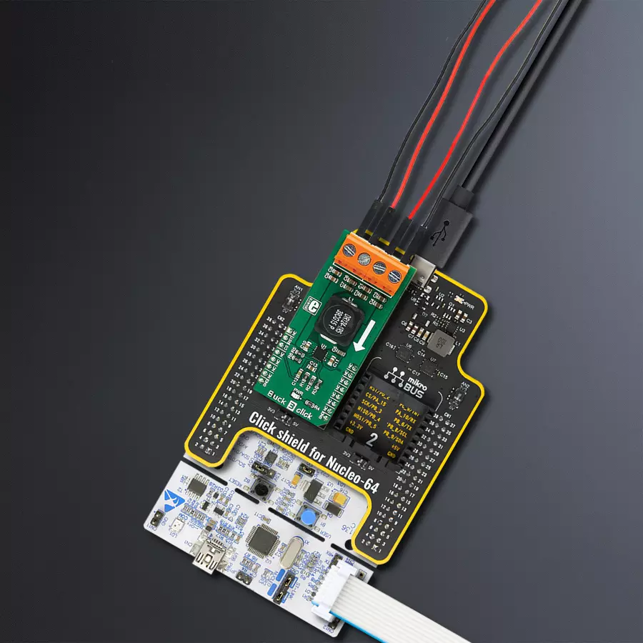
Buck 3 click
Dev. board
Nucleo 64 with STM32F446RE MCU
Compiler
NECTO Studio
MCU
STM32F446RE
Efficiently lower the input voltage to match the desired output, conserving energy in the process
A
A
Hardware Overview
How does it work?
Buck 3 Click is based on the TPS568215, a 4.5V to 17V Input, 8A synchronous step-down SWIFT™ converter from Texas Instruments. Its main features are unparalleled ripple and noise-free operation and high efficiency throughout the whole load range, up to 8A. As such, it is suitable for powering up power-demanding applications. Driven by the D-CAP3™ technology, the TPS568215 allows for a low number of external components, maintaining an accurate voltage at the output. To further minimize the noise, the TPS568215 has separate grounds for the logic and analog signals. The design of the Click board™ PCB ensures that the low noise operation is maintained within the specifications. The onboard voltage divider connected to the MODE pin of the IC is used to set the device to work with the fixed PWM frequency of 800kHz, DCM/Eco-mode™ for light loads, and to
set the limiting current to about 7A. When the connected load is light enough, the ripple current valleys on the inductor coils will cross zero. Since the TPS568215 is set to operate in DCM/Eco-mode™, the device will start skipping PWM pulses, maintaining efficiency. The device will be operated with the fixed frequency PWM signal, set by the MODE pin - 800kHz, providing low ripple and noise output voltage for regular loads. The PGD (power good) pin is used to signalize the undervoltage or overvoltage status of the device. When the voltage on the feedback pin is between 97% and 107% of the nominal output voltage, this pin is de-asserted and pulled to a HIGH logic level by the onboard pull-up resistor. This pin is driven to a LOW logic state when a faulty condition occurs. PGD pin is routed to the CS pin of the mikroBUS™. The EN pin is used to enable the
device. Setting this pin to a HIGH logic level (above 1.2V) will activate the internal switching circuitry. When the pin is set to a LOW logic level, the device is in STANDBY mode, with minimal power consumption. The EN pin is routed to the mikroBUS™ AN pin. This Click board™ is not powered up by the mikroBUS™ power rails. The internal LDO output from the TPS568215 (VREG) supplies the power for the logic sections of the IC. The input voltage supplies this internal LDO, so the Buck 3 Click will appear unpowered unless the external power supply is connected to the input terminal. Buck 3 click has two 2-pole terminals used to connect the external power supply and the load. These robust input and output screw terminals have cross-section dimensions that allow high currents to be connected with no heating or damage.

Features overview
Development board
Nucleo-64 with STM32F446RE MCU offers a cost-effective and adaptable platform for developers to explore new ideas and prototype their designs. This board harnesses the versatility of the STM32 microcontroller, enabling users to select the optimal balance of performance and power consumption for their projects. It accommodates the STM32 microcontroller in the LQFP64 package and includes essential components such as a user LED, which doubles as an ARDUINO® signal, alongside user and reset push-buttons, and a 32.768kHz crystal oscillator for precise timing operations. Designed with expansion and flexibility in mind, the Nucleo-64 board features an ARDUINO® Uno V3 expansion connector and ST morpho extension pin
headers, granting complete access to the STM32's I/Os for comprehensive project integration. Power supply options are adaptable, supporting ST-LINK USB VBUS or external power sources, ensuring adaptability in various development environments. The board also has an on-board ST-LINK debugger/programmer with USB re-enumeration capability, simplifying the programming and debugging process. Moreover, the board is designed to simplify advanced development with its external SMPS for efficient Vcore logic supply, support for USB Device full speed or USB SNK/UFP full speed, and built-in cryptographic features, enhancing both the power efficiency and security of projects. Additional connectivity is
provided through dedicated connectors for external SMPS experimentation, a USB connector for the ST-LINK, and a MIPI® debug connector, expanding the possibilities for hardware interfacing and experimentation. Developers will find extensive support through comprehensive free software libraries and examples, courtesy of the STM32Cube MCU Package. This, combined with compatibility with a wide array of Integrated Development Environments (IDEs), including IAR Embedded Workbench®, MDK-ARM, and STM32CubeIDE, ensures a smooth and efficient development experience, allowing users to fully leverage the capabilities of the Nucleo-64 board in their projects.

Microcontroller Overview
MCU Card / MCU

Architecture
ARM Cortex-M4
MCU Memory (KB)
512
Silicon Vendor
STMicroelectronics
Pin count
64
RAM (Bytes)
131072
You complete me!
Accessories
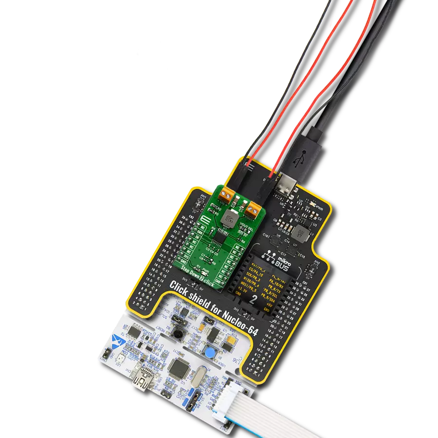
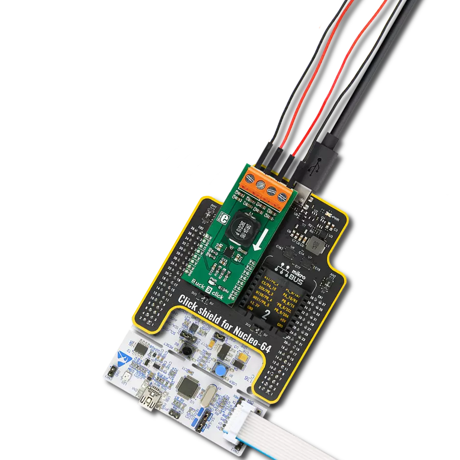
Click Shield for Nucleo-64 comes equipped with two proprietary mikroBUS™ sockets, allowing all the Click board™ devices to be interfaced with the STM32 Nucleo-64 board with no effort. This way, Mikroe allows its users to add any functionality from our ever-growing range of Click boards™, such as WiFi, GSM, GPS, Bluetooth, ZigBee, environmental sensors, LEDs, speech recognition, motor control, movement sensors, and many more. More than 1537 Click boards™, which can be stacked and integrated, are at your disposal. The STM32 Nucleo-64 boards are based on the microcontrollers in 64-pin packages, a 32-bit MCU with an ARM Cortex M4 processor operating at 84MHz, 512Kb Flash, and 96KB SRAM, divided into two regions where the top section represents the ST-Link/V2 debugger and programmer while the bottom section of the board is an actual development board. These boards are controlled and powered conveniently through a USB connection to program and efficiently debug the Nucleo-64 board out of the box, with an additional USB cable connected to the USB mini port on the board. Most of the STM32 microcontroller pins are brought to the IO pins on the left and right edge of the board, which are then connected to two existing mikroBUS™ sockets. This Click Shield also has several switches that perform functions such as selecting the logic levels of analog signals on mikroBUS™ sockets and selecting logic voltage levels of the mikroBUS™ sockets themselves. Besides, the user is offered the possibility of using any Click board™ with the help of existing bidirectional level-shifting voltage translators, regardless of whether the Click board™ operates at a 3.3V or 5V logic voltage level. Once you connect the STM32 Nucleo-64 board with our Click Shield for Nucleo-64, you can access hundreds of Click boards™, working with 3.3V or 5V logic voltage levels.

Used MCU Pins
mikroBUS™ mapper
Take a closer look
Click board™ Schematic

Step by step
Project assembly
Start by selecting your development board and Click board™. Begin with the Nucleo 64 with STM32F446RE MCU as your development board.


Track your results in real time
Application Output
1. Application Output - In Debug mode, the 'Application Output' window enables real-time data monitoring, offering direct insight into execution results. Ensure proper data display by configuring the environment correctly using the provided tutorial.

2. UART Terminal - Use the UART Terminal to monitor data transmission via a USB to UART converter, allowing direct communication between the Click board™ and your development system. Configure the baud rate and other serial settings according to your project's requirements to ensure proper functionality. For step-by-step setup instructions, refer to the provided tutorial.

3. Plot Output - The Plot feature offers a powerful way to visualize real-time sensor data, enabling trend analysis, debugging, and comparison of multiple data points. To set it up correctly, follow the provided tutorial, which includes a step-by-step example of using the Plot feature to display Click board™ readings. To use the Plot feature in your code, use the function: plot(*insert_graph_name*, variable_name);. This is a general format, and it is up to the user to replace 'insert_graph_name' with the actual graph name and 'variable_name' with the parameter to be displayed.

Software Support
Library Description
This library contains API for Buck 3 Click driver.
Key functions:
buck3_set_device_state- Function for setting device modebuck3_get_power_good- Function reads state of PGD pin
Open Source
Code example
The complete application code and a ready-to-use project are available through the NECTO Studio Package Manager for direct installation in the NECTO Studio. The application code can also be found on the MIKROE GitHub account.
/*!
 * \file
 * \brief Buck 3 Click example
 *
 * # Description
 * This example demonstrates the use of Buck 3 Click board.
 *
 * The demo application is composed of two sections :
 *
 * ## Application Init
 * Initializes the driver and configures the Click board.
 *
 * ## Application Task
 * Checks the PGD pin state which signalize the undervoltage or overvoltage fault or
 * the thermal shutdown condition.
 * If there's any of the above faults detected it logs a desired message on USB UART.
 *
 * \author Katarina Perendic
 *
 */
// ------------------------------------------------------------------- INCLUDES

#include "board.h"
#include "log.h"
#include "buck3.h"

// ------------------------------------------------------------------ VARIABLES

static buck3_t buck3;
static log_t logger;

// ------------------------------------------------------ APPLICATION FUNCTIONS

void application_init ( void )
{
    log_cfg_t log_cfg;
    buck3_cfg_t cfg;

    /**
     * Logger initialization.
     * Default baud rate: 115200
     * Default log level: LOG_LEVEL_DEBUG
     * @note If USB_UART_RX and USB_UART_TX
     * are defined as HAL_PIN_NC, you will
     * need to define them manually for log to work.
     * See @b LOG_MAP_USB_UART macro definition for detailed explanation.
     */
    LOG_MAP_USB_UART( log_cfg );
    log_init( &logger, &log_cfg );
    log_info( &logger, "---- Application Init ----" );

    //  Click initialization.

    buck3_cfg_setup( &cfg );
    BUCK3_MAP_MIKROBUS( cfg, MIKROBUS_1 );
    buck3_init( &buck3, &cfg );

    buck3_default_cfg( &buck3 );
    log_info( &logger, "---- Buck 3 is activated ----" );
    Delay_1sec( );
}

void application_task ( void )
{
    if ( !buck3_get_power_good( &buck3 ) )
    {
        log_info ( &logger, "---- Overvoltage or thermal shutdown detected ----" );
    }
    Delay_1sec( );
}

int main ( void )
{
    /* Do not remove this line or clock might not be set correctly. */
    #ifdef PREINIT_SUPPORTED
    preinit();
    #endif

    application_init( );

    for ( ; ; )
    {
        application_task( );
    }

    return 0;
}


// ------------------------------------------------------------------------ END