Provide precise color detection capabilities across various applications using BH1749NUC and STM32F091RC
Journey into color sensing perfection!

Published Feb 26, 2024
Click board™
Color 8 click
Dev. board
Nucleo-64 with STM32F091RC MCU
Compiler
NECTO Studio
MCU
STM32F091RC
Unlock a world of color possibilities with our advanced sensing solution, tailored to address the intricacies of color representation and ensuring consistent and vibrant color outcomes in your projects
A
A
Hardware Overview
How does it work?
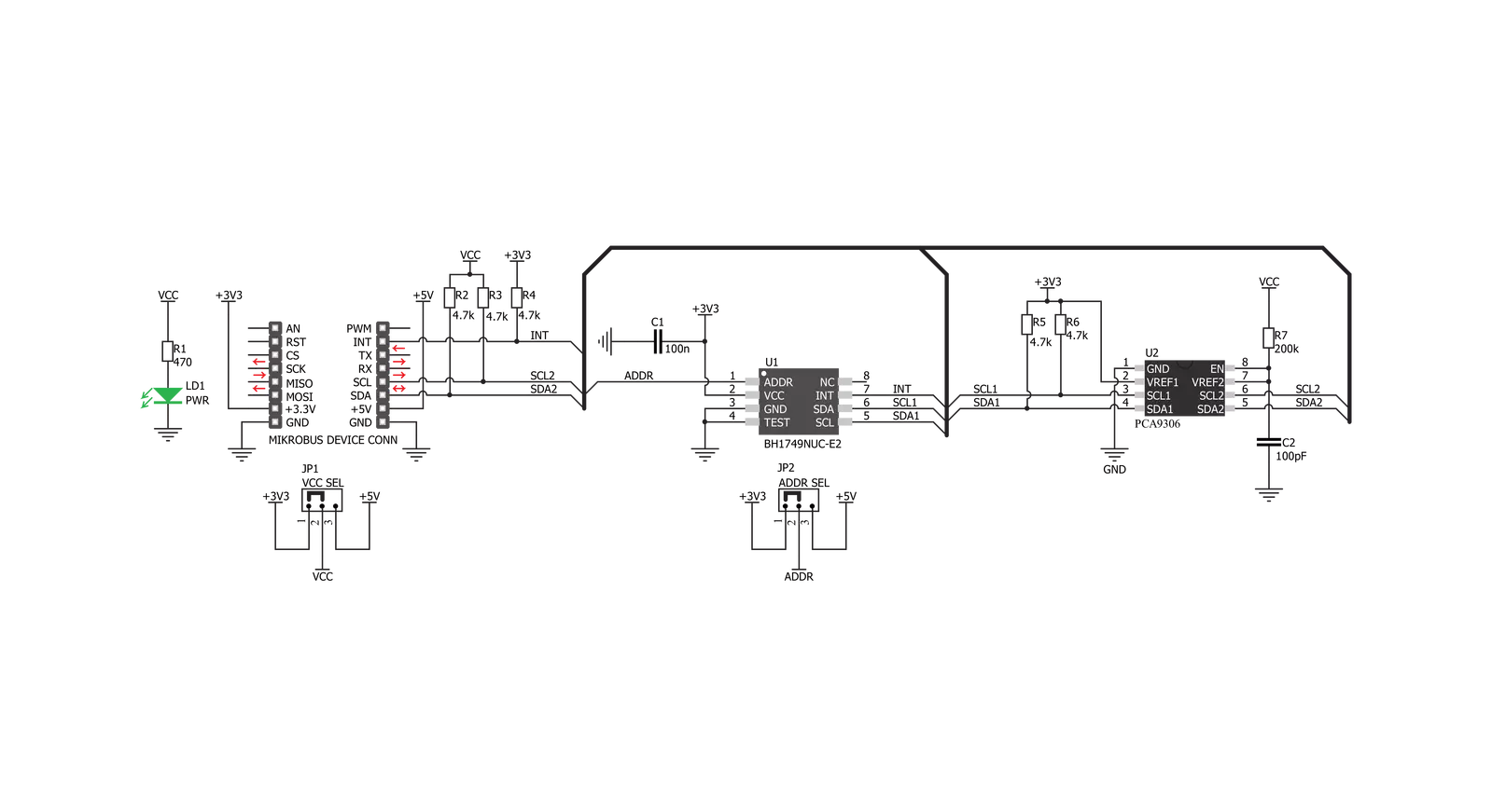
Color 8 Click is based on the BH1749NUC, an integrated color sensor IC, made by ROHM Semiconductor. This highly advanced four-channel color sensing device incorporates an IRCUT filter, that is used to block a portion of light in the IR spectrum, which can interfere with the readings of three independent photo-diodes, used to sense red, green and blue components of the light. However, it features an additional IR photo-sensing element, which is used to detect the intensity in the IR range. The IR measurement value can be used as a compensation parameter for the accurate color calculation. The color intensity sensing is roughly matched to the sensitivity of the human eye, so the sensor is the most sensitive in the range between 500nm and 600nm. The datasheet of the BH1749NUC offers an intensity over the wavelength diagram, so an accurate color calculation can be made in respect to the variable sensitivity of the sensor over the light wavelength. There are three independent A/D converters which are used to digitize the color intensity in 16-bit resolution. One of the converters, which is otherwise used for the blue light, is
internally multiplexed with the IR photo-diode. A programmable transimpedance gain amplifier (TIA) is available for both the RGB and IR channels, allowing amplification of the signal in the range from 1x to 32x. When using the highest gain ratio, in combination with the longest measurement time, which can be set up to 240ms, it is possible to achieve very high resolution of 0.0125 lx per count. The color and IR conversion results are available at the output registers in MSB/LSB format. Color 8 click communicates with the host MCU over the I2C interface, with its pin routed to the appropriate SCL and SDA pins of the mikroBUS™. The I2C address can be selected between two possible values: The slave I2C address depends on the state of the ADDR pin: if the pin at LOW logic level (0), the 7-bit I2C slave address is 0x38. If the pin is at the HIGH logic level (1), the I2C address is 0x39. The I2C slave address selection can be done by switching the SMD jumper labeled as ADDR SEL to an appropriate position: left position for logic 0, right position for logic 1. The powerful interrupt engine allows more optimized firmware for the controller (MCU)
to be written. The interrupt engine allows 16-bit values for the upper and lower threshold levels to be defined, as well as the persistence interval during which the event has occurred, before the interrupt is triggered, and more. Also, the user has the possibility to select which channel is included in the interrupt event detection (R, G, or B channel) The BH1749NUC requires a very low number of external components. It requires only pull-up resistors for the I2C bus lines and the INT pin, which is an open-drain interrupt line. This leaves room for yet another IC. The PCA9306, a bi-directional I2C level translator, from Texas Instruments, is often used in many Click board™ designs, due to its reliability and simplicity. It shifts the voltage levels of I2C and INT lines, thus allowing communication with MCUs that use both 3.3V and 5V as the communication voltage level. By moving the SMD jumper labeled as VCC SEL, it is possible to change the reference voltage for the PCA 9306, effectively changing the voltage level of the communication lines.


Features overview
Development board
Nucleo-64 with STM32F091RC MCU offers a cost-effective and adaptable platform for developers to explore new ideas and prototype their designs. This board harnesses the versatility of the STM32 microcontroller, enabling users to select the optimal balance of performance and power consumption for their projects. It accommodates the STM32 microcontroller in the LQFP64 package and includes essential components such as a user LED, which doubles as an ARDUINO® signal, alongside user and reset push-buttons, and a 32.768kHz crystal oscillator for precise timing operations. Designed with expansion and flexibility in mind, the Nucleo-64 board features an ARDUINO® Uno V3 expansion connector and ST morpho extension pin
headers, granting complete access to the STM32's I/Os for comprehensive project integration. Power supply options are adaptable, supporting ST-LINK USB VBUS or external power sources, ensuring adaptability in various development environments. The board also has an on-board ST-LINK debugger/programmer with USB re-enumeration capability, simplifying the programming and debugging process. Moreover, the board is designed to simplify advanced development with its external SMPS for efficient Vcore logic supply, support for USB Device full speed or USB SNK/UFP full speed, and built-in cryptographic features, enhancing both the power efficiency and security of projects. Additional connectivity is
provided through dedicated connectors for external SMPS experimentation, a USB connector for the ST-LINK, and a MIPI® debug connector, expanding the possibilities for hardware interfacing and experimentation. Developers will find extensive support through comprehensive free software libraries and examples, courtesy of the STM32Cube MCU Package. This, combined with compatibility with a wide array of Integrated Development Environments (IDEs), including IAR Embedded Workbench®, MDK-ARM, and STM32CubeIDE, ensures a smooth and efficient development experience, allowing users to fully leverage the capabilities of the Nucleo-64 board in their projects.

Microcontroller Overview
MCU Card / MCU

Architecture
ARM Cortex-M0
MCU Memory (KB)
256
Silicon Vendor
STMicroelectronics
Pin count
64
RAM (Bytes)
32768
You complete me!
Accessories
Click Shield for Nucleo-64 comes equipped with two proprietary mikroBUS™ sockets, allowing all the Click board™ devices to be interfaced with the STM32 Nucleo-64 board with no effort. This way, Mikroe allows its users to add any functionality from our ever-growing range of Click boards™, such as WiFi, GSM, GPS, Bluetooth, ZigBee, environmental sensors, LEDs, speech recognition, motor control, movement sensors, and many more. More than 1537 Click boards™, which can be stacked and integrated, are at your disposal. The STM32 Nucleo-64 boards are based on the microcontrollers in 64-pin packages, a 32-bit MCU with an ARM Cortex M4 processor operating at 84MHz, 512Kb Flash, and 96KB SRAM, divided into two regions where the top section represents the ST-Link/V2 debugger and programmer while the bottom section of the board is an actual development board. These boards are controlled and powered conveniently through a USB connection to program and efficiently debug the Nucleo-64 board out of the box, with an additional USB cable connected to the USB mini port on the board. Most of the STM32 microcontroller pins are brought to the IO pins on the left and right edge of the board, which are then connected to two existing mikroBUS™ sockets. This Click Shield also has several switches that perform functions such as selecting the logic levels of analog signals on mikroBUS™ sockets and selecting logic voltage levels of the mikroBUS™ sockets themselves. Besides, the user is offered the possibility of using any Click board™ with the help of existing bidirectional level-shifting voltage translators, regardless of whether the Click board™ operates at a 3.3V or 5V logic voltage level. Once you connect the STM32 Nucleo-64 board with our Click Shield for Nucleo-64, you can access hundreds of Click boards™, working with 3.3V or 5V logic voltage levels.

Used MCU Pins
mikroBUS™ mapper
Take a closer look
Click board™ Schematic
Step by step
Project assembly

Start by selecting your development board and Click board™. Begin with the Nucleo-64 with STM32F091RC MCU as your development board.


Track your results in real time
Application Output
1. Application Output - In Debug mode, the 'Application Output' window enables real-time data monitoring, offering direct insight into execution results. Ensure proper data display by configuring the environment correctly using the provided tutorial.

2. UART Terminal - Use the UART Terminal to monitor data transmission via a USB to UART converter, allowing direct communication between the Click board™ and your development system. Configure the baud rate and other serial settings according to your project's requirements to ensure proper functionality. For step-by-step setup instructions, refer to the provided tutorial.

3. Plot Output - The Plot feature offers a powerful way to visualize real-time sensor data, enabling trend analysis, debugging, and comparison of multiple data points. To set it up correctly, follow the provided tutorial, which includes a step-by-step example of using the Plot feature to display Click board™ readings. To use the Plot feature in your code, use the function: plot(*insert_graph_name*, variable_name);. This is a general format, and it is up to the user to replace 'insert_graph_name' with the actual graph name and 'variable_name' with the parameter to be displayed.

Software Support
Library Description
This library contains API for Color 8 Click driver.
Key functions:
color8_read_data- This function reads data from registercolor8_get_color_value- This functions reads 3 color filters and Clear Filters and converts the resulting color from RGB to HSLcolor8_get_color- This function detect colors.
Open Source
Code example
The complete application code and a ready-to-use project are available through the NECTO Studio Package Manager for direct installation in the NECTO Studio. The application code can also be found on the MIKROE GitHub account.
/*!
 * \file
 * \brief Color8 Click example
 *
 * # Description
 * This demo app reads RED, GREEEN, BLUE, IR data and return detect color.
 *
 * The demo application is composed of two sections :
 *
 * ## Application Init
 * Initialization device device configuration for start measurement.
 *
 * ## Application Task
 * Reads RED, GREEEN, BLUE and IR data.
 * Converts data to HSL value and return detect color.
 * For a successful color test, place a Click near the color of the monitor and detect the color on the screen.
 *
 * \author MikroE Team
 *
 */
// ------------------------------------------------------------------- INCLUDES

#include "board.h"
#include "log.h"
#include "color8.h"

// ------------------------------------------------------------------ VARIABLES

static color8_t color8;
static log_t logger;

// ------------------------------------------------------ APPLICATION FUNCTIONS

void application_init ( void )
{
    log_cfg_t log_cfg;
    color8_cfg_t cfg;

    /**
     * Logger initialization.
     * Default baud rate: 115200
     * Default log level: LOG_LEVEL_DEBUG
     * @note If USB_UART_RX and USB_UART_TX
     * are defined as HAL_PIN_NC, you will
     * need to define them manually for log to work.
     * See @b LOG_MAP_USB_UART macro definition for detailed explanation.
     */
    LOG_MAP_USB_UART( log_cfg );
    log_init( &logger, &log_cfg );
    log_info( &logger, "---- Application Init ----" );

    //  Click initialization.

    color8_cfg_setup( &cfg );
    COLOR8_MAP_MIKROBUS( cfg, MIKROBUS_1 );
    color8_init( &color8, &cfg );

    color8_write_byte( &color8, COLOR8_REG_SYSTEM_CONTROL, COLOR8_SS_SW_RESET_IS_DONE | COLOR8_SS_INT_PIN_IS_ACTIVE );
    color8_write_byte( &color8, COLOR8_REG_MODE_CONTROL_1, COLOR8_MC1_IR_DATA_GAIN_X1 |
                                                       COLOR8_MC1_RGB_DATA_GAIN_X1 |
                                                       COLOR8_MC1_MEASURE_MODE_35ms );

    color8_write_byte( &color8, COLOR8_REG_MODE_CONTROL_2, COLOR8_MC2_MEASUREMENT_IS_ACTIVE );
    log_printf( &logger, "---- Start measurement ----\r\n");
}

void application_task ( void )
{
    uint16_t red_data;
    uint16_t green_data;
    uint16_t blue_data;
    uint16_t ir_data;
    uint8_t is_color;
    float color_value;

    red_data = color8_read_data( &color8, COLOR8_REG_RED_DATA );
    log_printf( &logger, " RED data : %d \r\n", red_data );

    green_data = color8_read_data( &color8, COLOR8_REG_GREEN_DATA );
    log_printf( &logger, " GREEN data : %d \r\n", green_data );

    blue_data = color8_read_data( &color8, COLOR8_REG_BLUE_DATA );
    log_printf( &logger, " BLUE data : %d \r\n", blue_data );

    ir_data = color8_read_data( &color8, COLOR8_REG_IR_DATA );
    log_printf( &logger, " IR data : %d \r\n", ir_data );

    color_value = color8_get_color_value( &color8 );
    log_printf( &logger, " HSL color value : %f \r\n", color_value );

    is_color = color8_get_color( &color8, color_value );

    switch( is_color )
    {
        case 1:
        {
            log_printf( &logger, "--- Color: ORANGE \r\n" );
            break;
        }
        case 2:
        {
            log_printf( &logger, "--- Color: RED \r\n" );
            break;
        }
        case 3:
        {
            log_printf( &logger, "--- Color: PINK \r\n" );
            break;
        }
        case 4:
        {
            log_printf( &logger, "--- Color: PURPLE \r\n" );
            break;
        }
        case 5:
        {
            log_printf( &logger, "--- Color: BLUE \r\n" );
            break;
        }
        case 6:
        {
            log_printf( &logger, "--- Color: CYAN \r\n" );
            break;
        }
        case 7:
        {
            log_printf( &logger, "--- Color: GREEN \r\n" );
            break;
        }
        case 8:
        {
            log_printf( &logger, "--- Color: YELLOW \r\n" );
            break;
        }
        default:
        {
            break;
        }
    }
    Delay_ms ( 1000 );
}

int main ( void )
{
    /* Do not remove this line or clock might not be set correctly. */
    #ifdef PREINIT_SUPPORTED
    preinit();
    #endif

    application_init( );

    for ( ; ; )
    {
        application_task( );
    }

    return 0;
}

// ------------------------------------------------------------------------ END


