Make your motor-controlled projects reliable with DRV8830 and STM32L073RZ
Achieve optimal motor responsiveness

Published Feb 26, 2024
Click board™
DC Motor 11 Click
Dev.Board
Nucleo-64 with STM32L073RZ MCU
Compiler
NECTO Studio
MCU
STM32L073RZ
Embrace brushed motor control. Control motor current limiting and current sensing using this DC motor control solution!
A
A
Hardware Overview
How does it work?
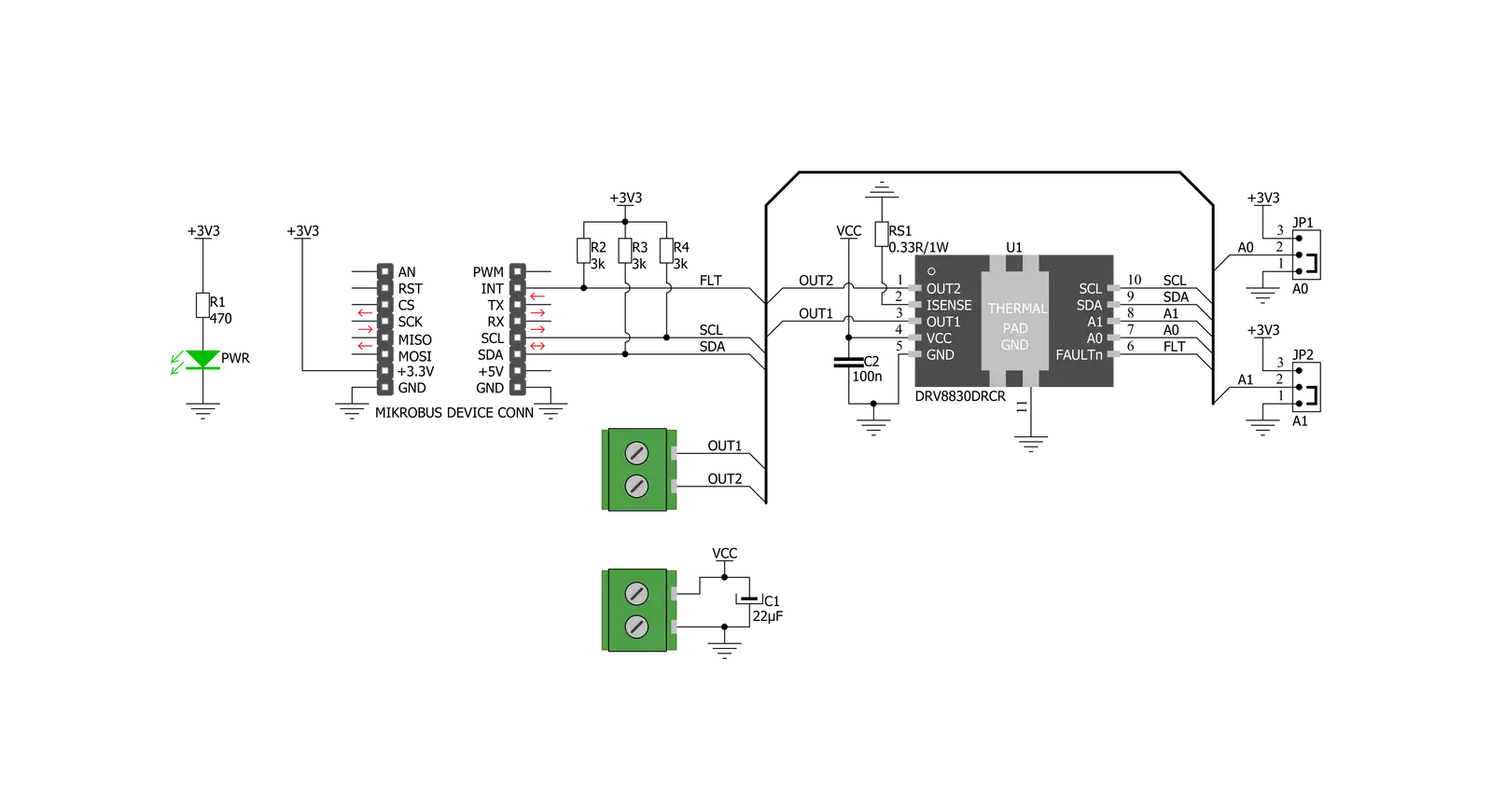
DC Motor 11 Click is based on the DRV8830, a low-voltage motor driver with a serial interface from Texas Instruments. This IC is an integrated H-Bridge driver with a current regulation circuit limiting the current through the connected load with a single resistor. A low ON resistance through the H-Bridge reduces the overall power dissipation, while an advanced control circuit injects dead-time intervals whenever the outputs change their state, preventing current shoot-throughs. The DRV8830 also integrates protection features, including undervoltage, overcurrent, and overtemperature protection. Each of these events will cause the H-Bridge MOSFETs to be disabled. After removing a fault condition, the device will continue its operation. The DRV8830 includes an internal reference voltage that is connected to a DAC. This DAC generates
a voltage that is used to set the PWM-regulated output voltage and, therefore, the speed and direction of the motor rotation. The DAC is controlled by the VSET bits from the I2C interface. For detailed commands for desired output voltages, refer to the DRV8830 datasheet. DC Motor 11 click uses the I2C interface to communicate with the main MCU and the fault pin (FLT), which is routed to the INT pin of the mikroBUS™ socket. The I2C address can be selected using additional SMD jumpers (JP1 and JP2) labeled ADDR SEL, determining the least significant bits of the DRV8830 slave I2C address. Although the DRV8830 supports up to 1A Maximum DC/RMS or Peak Drive Current Current through the connected load, it is limited to a maximum of 0.6A. A higher current will cause the overcurrent protection to be activated.
The peak current through the motor is limited to about 1A, ensuring reliable spin-up while preventing the overcurrent protection from being activated, even if a large load torque is applied. Although there is a low resistance across the H-Bridge, the current should be monitored to prevent excessive heating in situations where the load is reasonably high. This Click board™ can only be operated with a 3.3V logic voltage level. The board must perform appropriate logic voltage level conversion before using MCUs with different logic levels. However, the Click board™ comes equipped with a library containing functions and an example code that can be used as a reference for further development.

Features overview
Development board
Nucleo-64 with STM32L073RZ MCU offers a cost-effective and adaptable platform for developers to explore new ideas and prototype their designs. This board harnesses the versatility of the STM32 microcontroller, enabling users to select the optimal balance of performance and power consumption for their projects. It accommodates the STM32 microcontroller in the LQFP64 package and includes essential components such as a user LED, which doubles as an ARDUINO® signal, alongside user and reset push-buttons, and a 32.768kHz crystal oscillator for precise timing operations. Designed with expansion and flexibility in mind, the Nucleo-64 board features an ARDUINO® Uno V3 expansion connector and ST morpho extension pin
headers, granting complete access to the STM32's I/Os for comprehensive project integration. Power supply options are adaptable, supporting ST-LINK USB VBUS or external power sources, ensuring adaptability in various development environments. The board also has an on-board ST-LINK debugger/programmer with USB re-enumeration capability, simplifying the programming and debugging process. Moreover, the board is designed to simplify advanced development with its external SMPS for efficient Vcore logic supply, support for USB Device full speed or USB SNK/UFP full speed, and built-in cryptographic features, enhancing both the power efficiency and security of projects. Additional connectivity is
provided through dedicated connectors for external SMPS experimentation, a USB connector for the ST-LINK, and a MIPI® debug connector, expanding the possibilities for hardware interfacing and experimentation. Developers will find extensive support through comprehensive free software libraries and examples, courtesy of the STM32Cube MCU Package. This, combined with compatibility with a wide array of Integrated Development Environments (IDEs), including IAR Embedded Workbench®, MDK-ARM, and STM32CubeIDE, ensures a smooth and efficient development experience, allowing users to fully leverage the capabilities of the Nucleo-64 board in their projects.

Microcontroller Overview
MCU Card / MCU

Architecture
ARM Cortex-M0
MCU Memory (KB)
192
Silicon Vendor
STMicroelectronics
Pin count
64
RAM (Bytes)
20480
You complete me!
Accessories
Click Shield for Nucleo-64 comes equipped with two proprietary mikroBUS™ sockets, allowing all the Click board™ devices to be interfaced with the STM32 Nucleo-64 board with no effort. This way, Mikroe allows its users to add any functionality from our ever-growing range of Click boards™, such as WiFi, GSM, GPS, Bluetooth, ZigBee, environmental sensors, LEDs, speech recognition, motor control, movement sensors, and many more. More than 1537 Click boards™, which can be stacked and integrated, are at your disposal. The STM32 Nucleo-64 boards are based on the microcontrollers in 64-pin packages, a 32-bit MCU with an ARM Cortex M4 processor operating at 84MHz, 512Kb Flash, and 96KB SRAM, divided into two regions where the top section represents the ST-Link/V2 debugger and programmer while the bottom section of the board is an actual development board. These boards are controlled and powered conveniently through a USB connection to program and efficiently debug the Nucleo-64 board out of the box, with an additional USB cable connected to the USB mini port on the board. Most of the STM32 microcontroller pins are brought to the IO pins on the left and right edge of the board, which are then connected to two existing mikroBUS™ sockets. This Click Shield also has several switches that perform functions such as selecting the logic levels of analog signals on mikroBUS™ sockets and selecting logic voltage levels of the mikroBUS™ sockets themselves. Besides, the user is offered the possibility of using any Click board™ with the help of existing bidirectional level-shifting voltage translators, regardless of whether the Click board™ operates at a 3.3V or 5V logic voltage level. Once you connect the STM32 Nucleo-64 board with our Click Shield for Nucleo-64, you can access hundreds of Click boards™, working with 3.3V or 5V logic voltage levels.

DC Gear Motor - 430RPM (3-6V) represents an all-in-one combination of a motor and gearbox, where the addition of gear leads to a reduction of motor speed while increasing the torque output. This gear motor has a spur gearbox, making it a highly reliable solution for applications with lower torque and speed requirements. The most critical parameters for gear motors are speed, torque, and efficiency, which are, in this case, 520RPM with no load and 430RPM at maximum efficiency, alongside a current of 60mA and a torque of 50g.cm. Rated for a 3-6V operational voltage range and clockwise/counterclockwise rotation direction, this motor represents an excellent solution for many functions initially performed by brushed DC motors in robotics, medical equipment, electric door locks, and much more.

Used MCU Pins
mikroBUS™ mapper
Take a closer look
Schematic
Step by step
Project assembly
Start by selecting your development board and Click board™. Begin with the Nucleo-64 with STM32L073RZ MCU as your development board.


Track your results in real time
Application Output
After loading the code example, pressing the "DEBUG" button builds and programs it on the selected setup.

After programming is completed, a header with buttons for various actions available in the IDE appears. By clicking the green "PLAY "button, we start reading the results achieved with Click board™.

Upon completion of programming, the Application Output tab is automatically opened, where the achieved result can be read. In case of an inability to perform the Debug function, check if a proper connection between the MCU used by the setup and the CODEGRIP programmer has been established. A detailed explanation of the CODEGRIP-board connection can be found in the CODEGRIP User Manual. Please find it in the RESOURCES section.

Software Support
Library Description
This library contains API for DC Motor 11 Click driver.
Key functions:
dcmotor11_control- Motor Controldcmotor11_get_fault- Get Faultdcmotor11_get_interrupt_state- Interrupt state on the INT pin
Open Source
Code example
This example can be found in NECTO Studio. Feel free to download the code, or you can copy the code below.
/*!
 * \file
 * \brief DcMotor11 Click example
 *
 * # Description
 * This application is motor driver with the current limiting and current sensing.
 *
 * The demo application is composed of two sections :
 *
 * ## Application Init
 * Initialization driver init and sets first motor settings.
 *
 * ## Application Task
 * Waits for valid user input and executes functions based on set of valid commands.
 *
 *
 * \author MikroE Team
 *
 */
// ------------------------------------------------------------------- INCLUDES

#include "board.h"
#include "log.h"
#include "dcmotor11.h"

// ------------------------------------------------------------------ VARIABLES

static dcmotor11_t dcmotor11;
static log_t logger;

uint8_t motor_speed;
uint8_t motor_dir;
uint8_t f_motor_state = 1;

// ------------------------------------------------------ APPLICATION FUNCTIONS

void application_init ( void )
{
    log_cfg_t log_cfg;
    dcmotor11_cfg_t cfg;

    /**
     * Logger initialization.
     * Default baud rate: 115200
     * Default log level: LOG_LEVEL_DEBUG
     * @note If USB_UART_RX and USB_UART_TX
     * are defined as HAL_PIN_NC, you will
     * need to define them manually for log to work.
     * See @b LOG_MAP_USB_UART macro definition for detailed explanation.
     */
    LOG_MAP_USB_UART( log_cfg );
    log_init( &logger, &log_cfg );
    log_info( &logger, "---- Application Init ----" );

    //  Click initialization.

    dcmotor11_cfg_setup( &cfg );
    DCMOTOR11_MAP_MIKROBUS( cfg, MIKROBUS_1 );
    dcmotor11_init( &dcmotor11, &cfg );

    dcmotor11_get_fault( &dcmotor11 );

    // Start settings
    motor_dir = DCMOTOR11_DIRECTION_FORWARD;
    motor_speed = DCMOTOR11_VSET_480mV;
    dcmotor11_control( &dcmotor11, DCMOTOR11_DIRECTION_FORWARD, motor_speed );
}

void application_task ( void )
{
    // Speed increase
    motor_speed += 4;
    if ( motor_speed >= DCMOTOR11_VSET_4820mV )
    {
        log_printf( &logger, "---- MAX SPEED ---- \r\n" );
        motor_speed = DCMOTOR11_VSET_4820mV;
        dcmotor11_control( &dcmotor11, motor_dir, motor_speed );
    }
    else
    {
        log_printf( &logger, "---- Speed increase ---- \r\n" );
        log_printf( &logger, " MOTOR SPEED: %d \r\n", motor_speed );

        dcmotor11_control( &dcmotor11, motor_dir, motor_speed );
    }

    Delay_ms( 2000 );

    // Speed decrease
    motor_speed -= 4;
    if ( motor_speed < DCMOTOR11_VSET_480mV )
    {
        log_printf( &logger, "---- MIN SPEED ---- \r\n" );
        motor_speed = DCMOTOR11_VSET_480mV;
    }
    else
    {
        log_printf( &logger, "---- Speed decrease ---- \r\n");
        log_printf( &logger, " MOTOR SPEED: %d \r\n", motor_speed );

        dcmotor11_control( &dcmotor11, motor_dir, motor_speed );
    }

    Delay_ms( 2000 );

    // Stop / Start
    if( f_motor_state == 1 )
    {
        log_printf( &logger,"---- Stop Motor!!! ---- \r\n" );
        f_motor_state = 0;
        dcmotor11_stop( &dcmotor11 );
    }
    else
    {
        log_printf( &logger,"---- Start Motor ---- \r\n" );
        f_motor_state = 1;
        motor_speed = DCMOTOR11_VSET_480mV;
        dcmotor11_control( &dcmotor11, motor_dir, motor_speed );
    }

    Delay_ms ( 2000 );

    // Direction - Forward / Backword
    if ( motor_dir == 2 )
    {
        log_printf( &logger,"---- Direction - [FORWARD] ---- \r\n" );
        motor_dir = 1;
        dcmotor11_control( &dcmotor11, motor_dir, motor_speed );
    }
    else
    {
        log_printf( &logger,"---- Direction - [BACKWARD] ---- \r\n" );
        motor_dir = 2;
        dcmotor11_control( &dcmotor11, motor_dir, motor_speed );
    }
}

void main ( void )
{
    application_init( );

    for ( ; ; )
    {
        application_task( );
    }
}

// ------------------------------------------------------------------------ END


