Create accurate analysis for enhanced cardiac care with MAX86150 and STM32F091RC
Trust your heart's intuition

Published Feb 26, 2024
Click board™
ECG 6 Click
Dev. board
Nucleo-64 with STM32F091RC MCU
Compiler
NECTO Studio
MCU
STM32F091RC
Perfect for use in wearables, providing continuous heart monitoring for fitness tracking or medical purposes without the need for additional equipment
A
A
Hardware Overview
How does it work?
ECG 6 Click is based on the MAX86150, a complete electrocardiogram (ECG) from Analog Devices. It is designed for mobile health. The Click board™ has many features to provide health measurements: electrocardiogram, pulse oximetry, and heart rate. All these features allow ECG 6 click to be used in a range of health-related ECG, SpO2 subsystem, and HR applications, including fitness and activity heart rate monitors, portable ECG, wearable and remote health monitors, and similar. The MAX86150 contains an integrated SpO2 subsystem. The SpO2 subsystem is peripheral capillary oxygen saturation. It is measured by a device called a pulse oximeter. A clip is placed on the user's finger or foot, and light is sent through the finger and measured on the other side.
The MAX86150 integrates red and infrared LED drivers to modulate LED pulses for SpO2 and HR measurements. The LED current can be programmed from 0mA to 100mA with proper VLED supply voltage. The LED pulse width can be programmed from 50μs to 400μs to optimize the accuracy of results and power consumption based on use cases. ECG 6 Click allows several types of electrodes to be used. It supports both stainless-steel and silver-chloride electrode types. The electrodes are used to perform differential measurements of the voltage generated by the heart. Therefore, the heart can be monitored from a single plane only - the coronal plane. However, this is quite enough for fitness, heart rate monitoring, and similar applications. The extensive
interrupt engine can trigger the host MCU from various sources, including interrupt events due to lead detection, R-R detection, fast-recovery event, FIFO buffer states, and many more. These interrupt sources can trigger a state change on the interrupt pin (INT) of the MAX86150 IC. This pin is active-low. This Click board™ can operate with either 3.3V or 5V logic voltage levels selected via the VCC SEL jumper. This way, both 3.3V and 5V capable MCUs can use the communication lines properly. However, the Click board™ comes equipped with a library containing easy-to-use functions and an example code that can be used, as a reference, for further development.


Features overview
Development board
Nucleo-64 with STM32F091RC MCU offers a cost-effective and adaptable platform for developers to explore new ideas and prototype their designs. This board harnesses the versatility of the STM32 microcontroller, enabling users to select the optimal balance of performance and power consumption for their projects. It accommodates the STM32 microcontroller in the LQFP64 package and includes essential components such as a user LED, which doubles as an ARDUINO® signal, alongside user and reset push-buttons, and a 32.768kHz crystal oscillator for precise timing operations. Designed with expansion and flexibility in mind, the Nucleo-64 board features an ARDUINO® Uno V3 expansion connector and ST morpho extension pin
headers, granting complete access to the STM32's I/Os for comprehensive project integration. Power supply options are adaptable, supporting ST-LINK USB VBUS or external power sources, ensuring adaptability in various development environments. The board also has an on-board ST-LINK debugger/programmer with USB re-enumeration capability, simplifying the programming and debugging process. Moreover, the board is designed to simplify advanced development with its external SMPS for efficient Vcore logic supply, support for USB Device full speed or USB SNK/UFP full speed, and built-in cryptographic features, enhancing both the power efficiency and security of projects. Additional connectivity is
provided through dedicated connectors for external SMPS experimentation, a USB connector for the ST-LINK, and a MIPI® debug connector, expanding the possibilities for hardware interfacing and experimentation. Developers will find extensive support through comprehensive free software libraries and examples, courtesy of the STM32Cube MCU Package. This, combined with compatibility with a wide array of Integrated Development Environments (IDEs), including IAR Embedded Workbench®, MDK-ARM, and STM32CubeIDE, ensures a smooth and efficient development experience, allowing users to fully leverage the capabilities of the Nucleo-64 board in their projects.

Microcontroller Overview
MCU Card / MCU

Architecture
ARM Cortex-M0
MCU Memory (KB)
256
Silicon Vendor
STMicroelectronics
Pin count
64
RAM (Bytes)
32768
You complete me!
Accessories
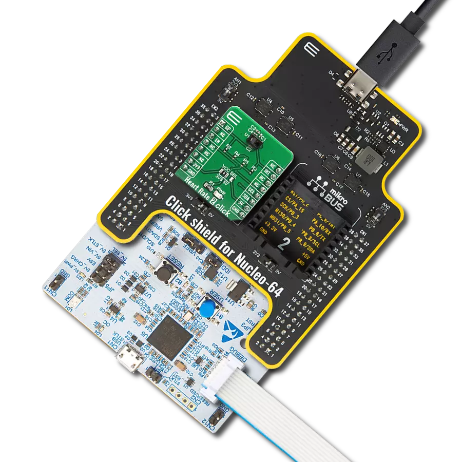
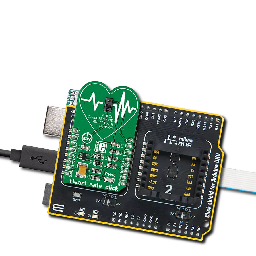
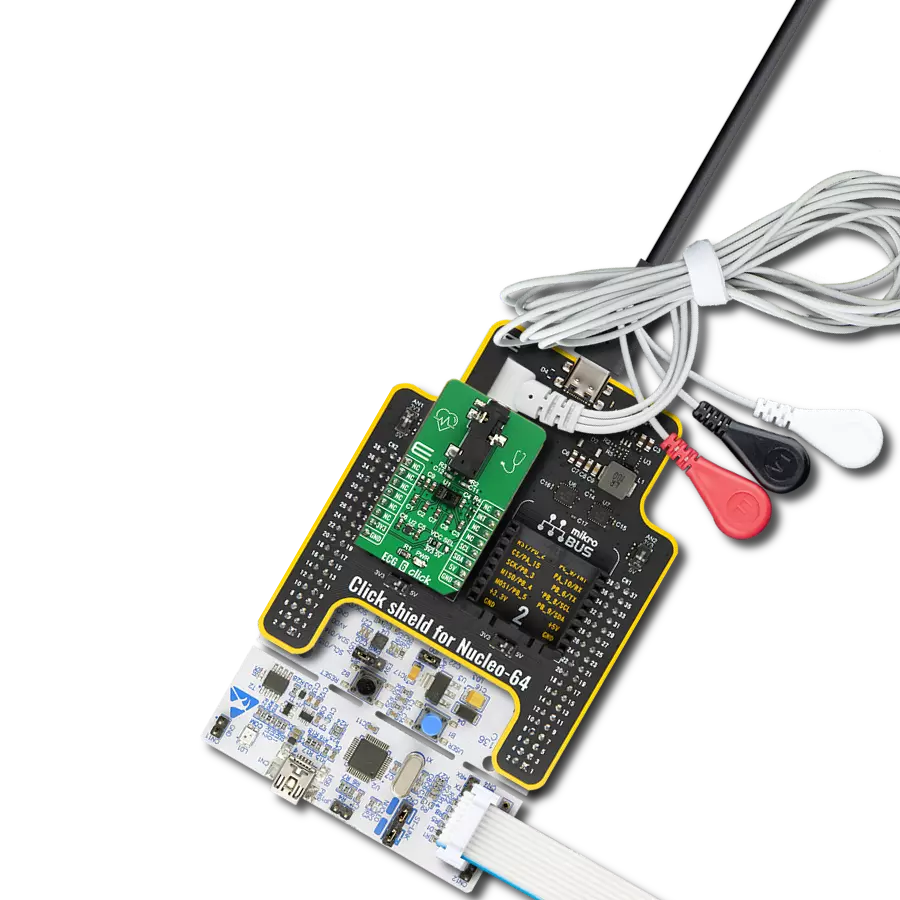
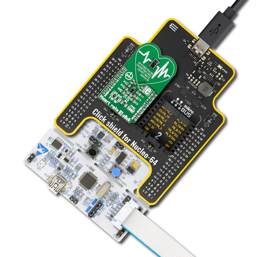
Click Shield for Nucleo-64 comes equipped with two proprietary mikroBUS™ sockets, allowing all the Click board™ devices to be interfaced with the STM32 Nucleo-64 board with no effort. This way, Mikroe allows its users to add any functionality from our ever-growing range of Click boards™, such as WiFi, GSM, GPS, Bluetooth, ZigBee, environmental sensors, LEDs, speech recognition, motor control, movement sensors, and many more. More than 1537 Click boards™, which can be stacked and integrated, are at your disposal. The STM32 Nucleo-64 boards are based on the microcontrollers in 64-pin packages, a 32-bit MCU with an ARM Cortex M4 processor operating at 84MHz, 512Kb Flash, and 96KB SRAM, divided into two regions where the top section represents the ST-Link/V2 debugger and programmer while the bottom section of the board is an actual development board. These boards are controlled and powered conveniently through a USB connection to program and efficiently debug the Nucleo-64 board out of the box, with an additional USB cable connected to the USB mini port on the board. Most of the STM32 microcontroller pins are brought to the IO pins on the left and right edge of the board, which are then connected to two existing mikroBUS™ sockets. This Click Shield also has several switches that perform functions such as selecting the logic levels of analog signals on mikroBUS™ sockets and selecting logic voltage levels of the mikroBUS™ sockets themselves. Besides, the user is offered the possibility of using any Click board™ with the help of existing bidirectional level-shifting voltage translators, regardless of whether the Click board™ operates at a 3.3V or 5V logic voltage level. Once you connect the STM32 Nucleo-64 board with our Click Shield for Nucleo-64, you can access hundreds of Click boards™, working with 3.3V or 5V logic voltage levels.

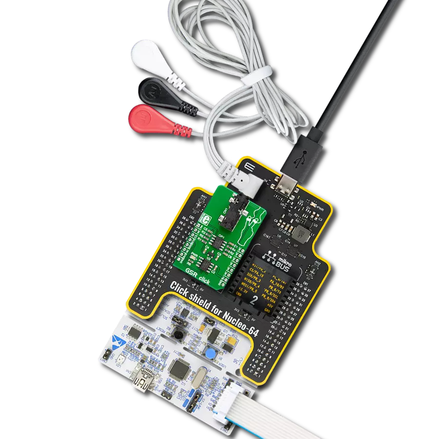
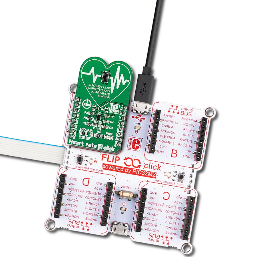
3-wire ECG/EMG cable comes with a convenient 3.5mm phone jack, and it is designed for electrocardiogram recording. This 1m cable is a practical companion for medical professionals and enthusiasts. To complement this cable, you can also use single-use adhesive ECG/EMG electrodes measuring 48x34mm, each equipped with an ECG/EMG cable stud adapter. These electrodes ensure a seamless experience when paired with our ECG/EMG cable and guarantee reliable ECG/EMG signal transmission for comprehensive cardiac monitoring. Trust in the accuracy and convenience of this setup to effortlessly record electrocardiograms and electromyograms with confidence.

Used MCU Pins
mikroBUS™ mapper
Take a closer look
Click board™ Schematic

Step by step
Project assembly
Start by selecting your development board and Click board™. Begin with the Nucleo-64 with STM32F091RC MCU as your development board.


Track your results in real time
Application Output
1. Application Output - In Debug mode, the 'Application Output' window enables real-time data monitoring, offering direct insight into execution results. Ensure proper data display by configuring the environment correctly using the provided tutorial.

2. UART Terminal - Use the UART Terminal to monitor data transmission via a USB to UART converter, allowing direct communication between the Click board™ and your development system. Configure the baud rate and other serial settings according to your project's requirements to ensure proper functionality. For step-by-step setup instructions, refer to the provided tutorial.

3. Plot Output - The Plot feature offers a powerful way to visualize real-time sensor data, enabling trend analysis, debugging, and comparison of multiple data points. To set it up correctly, follow the provided tutorial, which includes a step-by-step example of using the Plot feature to display Click board™ readings. To use the Plot feature in your code, use the function: plot(*insert_graph_name*, variable_name);. This is a general format, and it is up to the user to replace 'insert_graph_name' with the actual graph name and 'variable_name' with the parameter to be displayed.

Software Support
Library Description
This library contains API for ECG 6 Click driver.
Key functions:
ecg6_get_sample_data- This function gets one sample from FIFOplot_ecg_data- Sends ECG sensor data to SerialPlotplot_ppg_data- Sends PPG sensor data to SerialPlot
Open Source
Code example
The complete application code and a ready-to-use project are available through the NECTO Studio Package Manager for direct installation in the NECTO Studio. The application code can also be found on the MIKROE GitHub account.
/*!
 * \file
 * \brief Ecg6 Click example
 *
 * # Description
 * ECG 6 Click contain integrated electrocardiogram, pulse oximeter,
 * heart rate monitor sensor module.
 *
 * The demo application is composed of two sections :
 *
 * ## Application Init
 * Initialize I2C module and all necessary pins. Checking communication accuracy
 * and running default configuration for measurement.
 *
 * ## Application Task
 * Measures an ECG signal or PPG sensor and draws a graph on a SerialPlot
 *
 * ##Additional Functions :
 * - plot_ecg_data ( ) -  Sends ECG sensor data to SerialPlot
 * - plot_ppg_data ( ) -  Sends PPG sensor data to SerialPlot
 *
 *
 * *note:*
 * When using ECG measurement - PPG measurement must be switched off ...
 * Drawing speeds vary for PPG and ECG sensor.
 *
 * \author MikroE Team
 *
 */
// ------------------------------------------------------------------- INCLUDES

#include "board.h"
#include "log.h"
#include "ecg6.h"

// ------------------------------------------------------------------ VARIABLES

static ecg6_t ecg6;
static log_t logger;
static ecg6_int_status_t int_status;

static uint8_t ECG_EXAMPLE = 1;
static uint8_t PPG_EXAMPLE = 0;
static uint8_t DEMO_EXAMPLE;

static uint32_t time_cnt = 0;
static uint8_t device_check;

// ------------------------------------------------------ APPLICATION FUNCTIONS

static void plot_ecg_data ( uint32_t ecg_data )
{
    uint32_t tmp;
    uint32_t timer;

    tmp = ecg_data & 0x3FFFFF;
    timer = time_cnt++;

    if ( tmp != 0 ) {
        log_printf( &logger, "%lu,%lu\r\n", tmp, timer );
        Delay_ms ( 5 );
    }
}

static void plot_ppg_data ( uint32_t ir_data, uint32_t red_data )
{
    uint32_t tmp;
    uint32_t tmf;
    uint32_t tmd;

    tmp = ir_data & 0x0007FFFF;
    tmf = red_data & 0x0007FFFF;
    tmd = time_cnt++;

    if ( ( tmp != 0 ) && ( tmf != 0 ) ) {
        log_printf( &logger,"%lu,%lu,%lu\r\n", tmp, tmf, tmd );
        Delay_ms ( 20 );
    }
}

void application_init ( void )
{
    log_cfg_t log_cfg;
    ecg6_cfg_t cfg;

    /**
     * Logger initialization.
     * Default baud rate: 115200
     * Default log level: LOG_LEVEL_DEBUG
     * @note If USB_UART_RX and USB_UART_TX
     * are defined as HAL_PIN_NC, you will
     * need to define them manually for log to work.
     * See @b LOG_MAP_USB_UART macro definition for detailed explanation.
     */
    LOG_MAP_USB_UART( log_cfg );
    log_init( &logger, &log_cfg );
    log_info( &logger, "---- Application Init ----" );

    //  Click initialization.

    ecg6_cfg_setup( &cfg );
    ECG6_MAP_MIKROBUS( cfg, MIKROBUS_1 );
    ecg6_init( &ecg6, &cfg );

    Delay_ms ( 1000 );

    DEMO_EXAMPLE = PPG_EXAMPLE;

    // Dummy read
    ecg6_check_path_id( &ecg6 );
    Delay_ms ( 100 );

    device_check = ecg6_check_path_id( &ecg6 );

    if ( device_check != 0 )
    {
       log_printf( &logger, " -- > Device ERROR!!! \r\n" );
       for ( ; ; );
    }
    log_printf( &logger, " -- > Device OK!!! \r\n" );

    if ( DEMO_EXAMPLE == ECG_EXAMPLE )
    {
        ecg6_default_cfg( &ecg6 );
    }
    else
    {
        ecg6_ppg_default_config( &ecg6 );
    }

    log_printf( &logger, " ---- Configuration done ----- \r\n" );
    Delay_ms ( 1000 );

    time_cnt = 0;
}

void application_task ( void )
{
    ecg6_element_t sample;

    if ( ecg6_int_pin_state(&ecg6) == 0 ) {

        ecg6_get_sample_data( &ecg6, &sample, 0x00 );

        if ( DEMO_EXAMPLE == ECG_EXAMPLE )
        {
            plot_ecg_data( sample.element_1 );
        }

        else
        {
            plot_ppg_data( sample.element_1, sample.element_2 );
        }
    }
}

int main ( void )
{
    /* Do not remove this line or clock might not be set correctly. */
    #ifdef PREINIT_SUPPORTED
    preinit();
    #endif

    application_init( );

    for ( ; ; )
    {
        application_task( );
    }

    return 0;
}


// ------------------------------------------------------------------------ END
Additional Support
Resources
Category:Biometrics