Take your senses to the next level with DA7282 and STM32F091RC
Experience haptic feedback like never before!

Published Feb 26, 2024
Click board™
Haptic 3 Click
Dev. board
Nucleo-64 with STM32F091RC MCU
Compiler
NECTO Studio
MCU
STM32F091RC
The haptic driver that brings your digital world to life with realistic touch feedback!
A
A
Hardware Overview
How does it work?
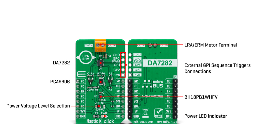
Haptic 3 Click is based on the DA7282, a haptic driver capable of driving both LRA and ERM actuators from Dialog Semiconductor. The power-optimized architecture and advanced closed-loop digital algorithms achieve a high-fidelity haptic drive. The DA7282 features frequency control within an onboard Waveform Memory and three distinct general-purpose inputs for triggering up to six specific sequences, which helps with emulating button pressing in many applications. The device controls drive levels based on the sequence selected by the I2C interface across the load and senses the movement of the actuator. The driven waveform is generated by a current-regulated loop using a high-frequency PWM modulation. The differential output drive features a switching regulator architecture with an H-bridge differential drive across the load at 187.5kHz. The DA7282 can also perform close-loop actuator monitoring while driving to enable calibration-free playback, frequency tracking
(LRA only), Active Acceleration, Rapid Stop, and actuator diagnostics. Resonant frequency tracking can be enabled while driving an LRA to track the mechanical resonance of the actuator through closed-loop control or can be disabled to operate DA7282 in open-loop wideband frequency operation while driving LRAs with a broader bandwidth frequency response. Also, Active Acceleration and Rapid Stop features enable automated driving of both ERM and LRA loads (when frequency tracking is enabled), which reduces the time to reach the target acceleration level and the time for the actuator to come to a complete stop. Although it can use both mikroBUS™ power rails for regular power supply, its digital part requires a voltage level of 1.8V to work correctly. Therefore, a small regulating LDO, the BH18PB1WHFV, provides a 1.8V out of 5V and 3.3V mikroBUS™ power rails alongside Enable feature through the EN pin of the mikroBUS™ socket, offering a switch operation to turn ON/OFF
power delivery to the connected load. Haptic 3 Click communicates with MCU using the standard I2C 2-Wire interface with a maximum clock frequency of 400kHz. Since the sensor for communication requires a logic level of 1.8V, this Click board™ also features the PCA9306 voltage-level translator. The I2C interface bus lines are routed to the voltage-level translators allowing this Click board™ to work with both 3.3V and 5V MCUs properly. Also, it uses an interrupt pin, routed to the IRQ pin of the mikroBUS™ socket, when a different fault condition occurs to alert the MCU. This Click board™ can operate with either 3.3V or 5V logic voltage levels selected via the VCC SEL jumper. This way, both 3.3V and 5V capable MCUs can use the communication lines properly. However, the Click board™ comes equipped with a library containing easy-to-use functions and an example code that can be used, as a reference, for further development.
Features overview
Development board
Nucleo-64 with STM32F091RC MCU offers a cost-effective and adaptable platform for developers to explore new ideas and prototype their designs. This board harnesses the versatility of the STM32 microcontroller, enabling users to select the optimal balance of performance and power consumption for their projects. It accommodates the STM32 microcontroller in the LQFP64 package and includes essential components such as a user LED, which doubles as an ARDUINO® signal, alongside user and reset push-buttons, and a 32.768kHz crystal oscillator for precise timing operations. Designed with expansion and flexibility in mind, the Nucleo-64 board features an ARDUINO® Uno V3 expansion connector and ST morpho extension pin
headers, granting complete access to the STM32's I/Os for comprehensive project integration. Power supply options are adaptable, supporting ST-LINK USB VBUS or external power sources, ensuring adaptability in various development environments. The board also has an on-board ST-LINK debugger/programmer with USB re-enumeration capability, simplifying the programming and debugging process. Moreover, the board is designed to simplify advanced development with its external SMPS for efficient Vcore logic supply, support for USB Device full speed or USB SNK/UFP full speed, and built-in cryptographic features, enhancing both the power efficiency and security of projects. Additional connectivity is
provided through dedicated connectors for external SMPS experimentation, a USB connector for the ST-LINK, and a MIPI® debug connector, expanding the possibilities for hardware interfacing and experimentation. Developers will find extensive support through comprehensive free software libraries and examples, courtesy of the STM32Cube MCU Package. This, combined with compatibility with a wide array of Integrated Development Environments (IDEs), including IAR Embedded Workbench®, MDK-ARM, and STM32CubeIDE, ensures a smooth and efficient development experience, allowing users to fully leverage the capabilities of the Nucleo-64 board in their projects.

Microcontroller Overview
MCU Card / MCU

Architecture
ARM Cortex-M0
MCU Memory (KB)
256
Silicon Vendor
STMicroelectronics
Pin count
64
RAM (Bytes)
32768
You complete me!
Accessories
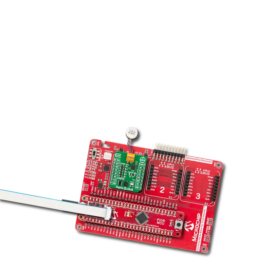
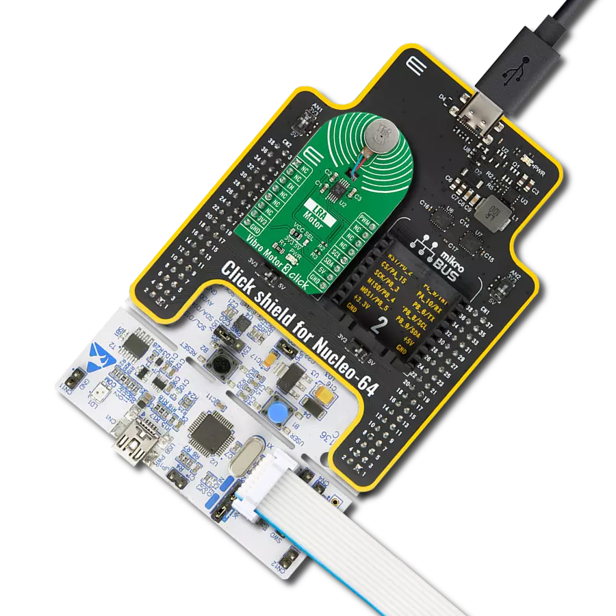
Click Shield for Nucleo-64 comes equipped with two proprietary mikroBUS™ sockets, allowing all the Click board™ devices to be interfaced with the STM32 Nucleo-64 board with no effort. This way, Mikroe allows its users to add any functionality from our ever-growing range of Click boards™, such as WiFi, GSM, GPS, Bluetooth, ZigBee, environmental sensors, LEDs, speech recognition, motor control, movement sensors, and many more. More than 1537 Click boards™, which can be stacked and integrated, are at your disposal. The STM32 Nucleo-64 boards are based on the microcontrollers in 64-pin packages, a 32-bit MCU with an ARM Cortex M4 processor operating at 84MHz, 512Kb Flash, and 96KB SRAM, divided into two regions where the top section represents the ST-Link/V2 debugger and programmer while the bottom section of the board is an actual development board. These boards are controlled and powered conveniently through a USB connection to program and efficiently debug the Nucleo-64 board out of the box, with an additional USB cable connected to the USB mini port on the board. Most of the STM32 microcontroller pins are brought to the IO pins on the left and right edge of the board, which are then connected to two existing mikroBUS™ sockets. This Click Shield also has several switches that perform functions such as selecting the logic levels of analog signals on mikroBUS™ sockets and selecting logic voltage levels of the mikroBUS™ sockets themselves. Besides, the user is offered the possibility of using any Click board™ with the help of existing bidirectional level-shifting voltage translators, regardless of whether the Click board™ operates at a 3.3V or 5V logic voltage level. Once you connect the STM32 Nucleo-64 board with our Click Shield for Nucleo-64, you can access hundreds of Click boards™, working with 3.3V or 5V logic voltage levels.

Vibration ERM Motor 9K RPM 3V (VC1026B002F - old MPN C1026B002F) represents a compact-size Eccentric Rotating Mass (ERM) motor designed by Vybronics. This type of motor contains a small eccentric weight on its rotor, so while rotating, it also produces a vibration effect often used for haptic feedback on many small handheld devices. Due to its circular shape with a diameter of 10mm, the VC1026B002F is often referred to as a coin motor. The main characteristics of this vibration motor are its supply voltage, in this case, 3VDC, maximum rated current of 85mA, and the rated speed of 9000RPM, which produces the highest G force/vibration energy of 0.80GRMS. It can also be used with self-adhesive tape to mount it on your PCB or the inner wall of your product's housing.

Used MCU Pins
mikroBUS™ mapper
Take a closer look
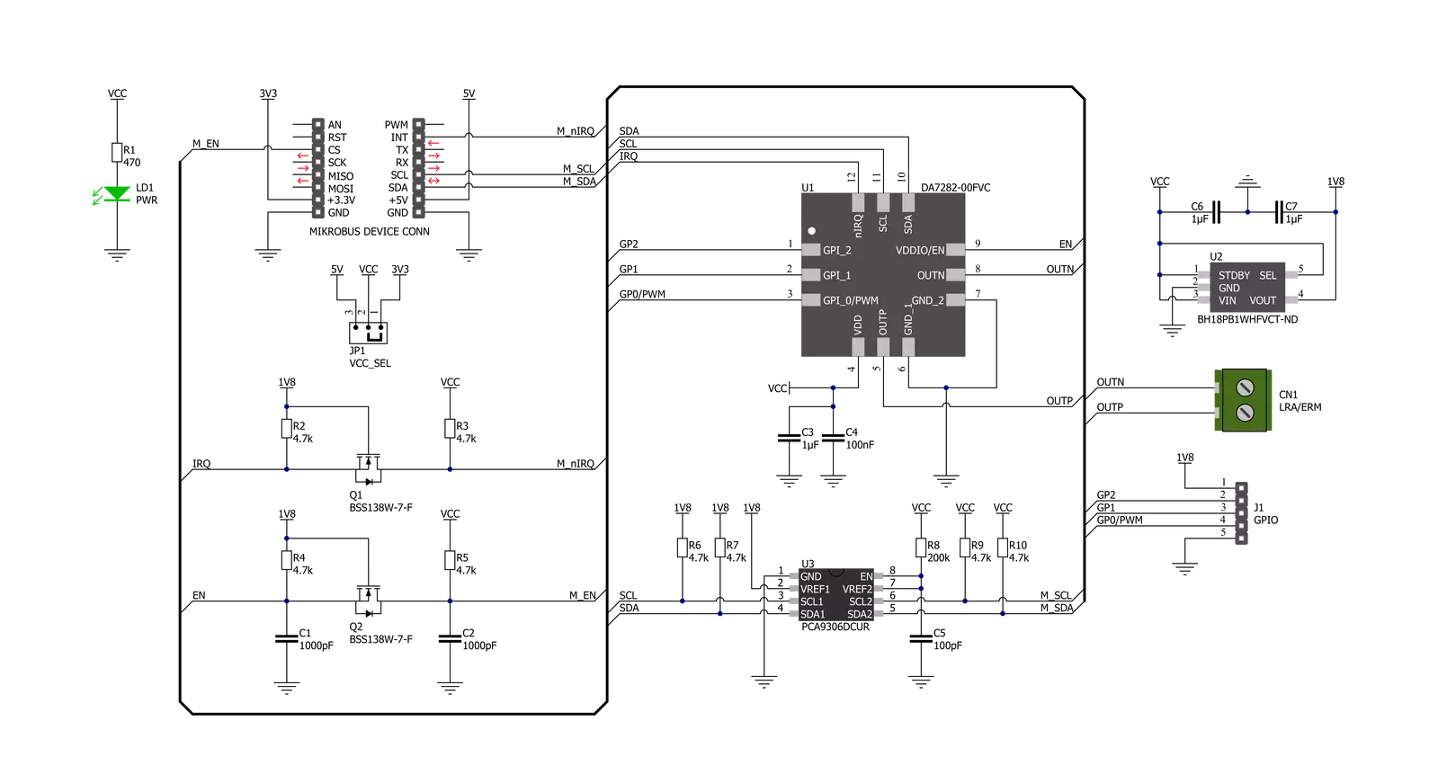
Click board™ Schematic
Step by step
Project assembly
Start by selecting your development board and Click board™. Begin with the Nucleo-64 with STM32F091RC MCU as your development board.


Software Support
Library Description
This library contains API for Haptic 3 Click driver.
Key functions:
haptic3_set_vibration_levelThis function sets the motor vibration level.haptic3_get_vibration_levelThis function reads the motor vibration level.haptic3_write_registerThis function writes desired data to the selected register by using I2C serial interface.
Open Source
Code example
The complete application code and a ready-to-use project are available through the NECTO Studio Package Manager for direct installation in the NECTO Studio. The application code can also be found on the MIKROE GitHub account.
/*!
 * @file main.c
 * @brief HAPTIC3 Click example
 *
 * # Description
 * This example demonstrates the use of HAPTIC 3 Click board by controlling
 * the attached motor vibration level.
 *
 * The demo application is composed of two sections :
 *
 * ## Application Init
 * Initializes the driver and performs the Click default configuration.
 *
 * ## Application Task
 * Changes the motor vibration level every 2 seconds from MAX to MIN,
 * and displays the currently set level on the USB UART.
 *
 * @author Stefan Filipovic
 *
 */

#include "board.h"
#include "log.h"
#include "haptic3.h"

static haptic3_t haptic3;
static log_t logger;

void application_init ( void )
{
    log_cfg_t log_cfg;  /**< Logger config object. */
    haptic3_cfg_t haptic3_cfg;  /**< Click config object. */

    /**
     * Logger initialization.
     * Default baud rate: 115200
     * Default log level: LOG_LEVEL_DEBUG
     * @note If USB_UART_RX and USB_UART_TX
     * are defined as HAL_PIN_NC, you will
     * need to define them manually for log to work.
     * See @b LOG_MAP_USB_UART macro definition for detailed explanation.
     */
    LOG_MAP_USB_UART( log_cfg );
    log_init( &logger, &log_cfg );
    log_info( &logger, " Application Init " );

    // Click initialization.
    haptic3_cfg_setup( &haptic3_cfg );
    HAPTIC3_MAP_MIKROBUS( haptic3_cfg, MIKROBUS_1 );
    if ( I2C_MASTER_ERROR == haptic3_init( &haptic3, &haptic3_cfg ) )
    {
        log_error( &logger, " Communication init." );
        for ( ; ; );
    }

    if ( HAPTIC3_ERROR == haptic3_default_cfg ( &haptic3 ) )
    {
        log_error( &logger, " Default configuration." );
        for ( ; ; );
    }

    log_info( &logger, " Application Task " );
}

void application_task ( void )
{
    float vibration_level;
    if ( HAPTIC3_OK == haptic3_set_vibration_level ( &haptic3, HAPTIC3_VIBRATION_LEVEL_MAX ) )
    {
        if ( HAPTIC3_OK == haptic3_get_vibration_level ( &haptic3, &vibration_level ) )
        {
            log_printf( &logger, " Vibration level: %.3f \r\n\n", vibration_level );
        }
    }
    Delay_ms ( 1000 );
    Delay_ms ( 1000 );

    if ( HAPTIC3_OK == haptic3_set_vibration_level ( &haptic3, HAPTIC3_VIBRATION_LEVEL_MIN ) )
    {
        if ( HAPTIC3_OK == haptic3_get_vibration_level ( &haptic3, &vibration_level ) )
        {
            log_printf( &logger, " Vibration level: %.3f \r\n\n", vibration_level );
        }
    }
    Delay_ms ( 1000 );
    Delay_ms ( 1000 );
}

int main ( void )
{
    /* Do not remove this line or clock might not be set correctly. */
    #ifdef PREINIT_SUPPORTED
    preinit();
    #endif

    application_init( );

    for ( ; ; )
    {
        application_task( );
    }

    return 0;
}

// ------------------------------------------------------------------------ END
Additional Support
Resources
Category:Haptic