Simplify and improve your I2C management needs using TCA9545A and STM32F091RC
Switch, mux, and beyond
Published Feb 26, 2024
Click board™
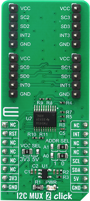
I2C MUX 2 Click
Dev. board
Nucleo-64 with STM32F091RC MCU
Compiler
NECTO Studio
MCU
STM32F091RC
Committed to enhancing your I2C communication capabilities, our mission is to provide seamless access to I2C multiplexing, offering a user-friendly and flexible solution for effectively addressing complex I2C scenarios
A
A
Hardware Overview
How does it work?
I2C MUX 2 Click is based on the TCA9545A, a 4-channel, bidirectional translating I2C switch from Texas instruments. The master SCL/SDA signal pair is directed to four channels of slave devices, SC0/SD0-SC3/SD3. Any individual downstream channel can be selected as well as any combination of the four channels. The TCA9545A also supports interrupt signals in order for the master to detect an interrupt on the INT output terminal that can result from any of the slave devices connected to the INT3-INT0 input terminals. The device offers an active-low RESET input which resets the state machine and allows the TCA9545A to recover should one of the downstream I2C buses get stuck in a low state. The state machine of the device can also be reset by cycling the power supply, VCC, also known as a power-on reset (POR). Both the RESET function and a POR will cause all channels to be deselected. The connections of the I2C data path are controlled by the same I2C master device that is switched to communicate with multiple I2C slaves. The I2C slave address can be configured by soldering SMD jumpers labeled as ADDR SEL to set the least significant bit (LSB). After the successful acknowledgment of the slave address, a single 8-bit control register is written to or read from to determine the selected channels and state
of the interrupts. The TCA9545A may also be used for voltage translation, allowing the use of different bus voltages on each SCn/SDn pair such that 1.8-V, 2.5-V, or 3.3-V parts can communicate with 5-V parts. This is achieved by using external pull-up resistors to pull the bus up to the desired voltage for the master and each slave channel. One or several SCn/SDn downstream pairs, or channels, are selected by the contents of the control register. After the TCA9545A has been addressed, the control register is written. The four LSBs of the control byte are used to determine which channel or channels are to be selected. When a channel is selected, it becomes active after a stop condition has been placed on the I2C bus. This ensures that all SCn/SDn lines are in a high state when the channel is made active so that no false conditions are generated at the time of connection. A stop condition must occur always right after the acknowledge cycle. The TCA9545A provides four interrupt inputs (one for each channel) and one open-drain interrupt output. When an interrupt is generated by any device, it is detected by the TCA9545A and the interrupt output is driven low. The channel does not need to be active for the detection of the interrupt. A bit also is set in the control register. Bits 4–7 of the control register correspond to channels 0–3 of the
TCA9545A, respectively. Therefore, if an interrupt is generated by any device connected to channel 1, the state of the interrupt inputs is loaded into the control register when a read is accomplished. Likewise, an interrupt on any device connected to channel 0 would cause bit 4 of the control register to be set on the read. The master then can address the TCA9545A and read the contents of the control register to determine which channel contains the device generating the interrupt. The master then can reconfigure the TCA9545A to select this channel and locate the device generating the interrupt and clear it. It should be noted that more than one device can provide an interrupt on a channel, so it is up to the master to ensure that all devices on a channel are interrogated for an interrupt. The interrupt inputs can be used as general-purpose inputs if the interrupt function is not required. If unused, interrupt input(s) must be connected to VCC. This Click board™ can operate with either 3.3V or 5V logic voltage levels selected via the VCC SEL jumper. This way, both 3.3V and 5V capable MCUs can use the communication lines properly. Also, this Click board™ comes equipped with a library containing easy-to-use functions and an example code that can be used as a reference for further development.


Features overview
Development board
Nucleo-64 with STM32F091RC MCU offers a cost-effective and adaptable platform for developers to explore new ideas and prototype their designs. This board harnesses the versatility of the STM32 microcontroller, enabling users to select the optimal balance of performance and power consumption for their projects. It accommodates the STM32 microcontroller in the LQFP64 package and includes essential components such as a user LED, which doubles as an ARDUINO® signal, alongside user and reset push-buttons, and a 32.768kHz crystal oscillator for precise timing operations. Designed with expansion and flexibility in mind, the Nucleo-64 board features an ARDUINO® Uno V3 expansion connector and ST morpho extension pin
headers, granting complete access to the STM32's I/Os for comprehensive project integration. Power supply options are adaptable, supporting ST-LINK USB VBUS or external power sources, ensuring adaptability in various development environments. The board also has an on-board ST-LINK debugger/programmer with USB re-enumeration capability, simplifying the programming and debugging process. Moreover, the board is designed to simplify advanced development with its external SMPS for efficient Vcore logic supply, support for USB Device full speed or USB SNK/UFP full speed, and built-in cryptographic features, enhancing both the power efficiency and security of projects. Additional connectivity is
provided through dedicated connectors for external SMPS experimentation, a USB connector for the ST-LINK, and a MIPI® debug connector, expanding the possibilities for hardware interfacing and experimentation. Developers will find extensive support through comprehensive free software libraries and examples, courtesy of the STM32Cube MCU Package. This, combined with compatibility with a wide array of Integrated Development Environments (IDEs), including IAR Embedded Workbench®, MDK-ARM, and STM32CubeIDE, ensures a smooth and efficient development experience, allowing users to fully leverage the capabilities of the Nucleo-64 board in their projects.

Microcontroller Overview
MCU Card / MCU

Architecture
ARM Cortex-M0
MCU Memory (KB)
256
Silicon Vendor
STMicroelectronics
Pin count
64
RAM (Bytes)
32768
You complete me!
Accessories
Click Shield for Nucleo-64 comes equipped with two proprietary mikroBUS™ sockets, allowing all the Click board™ devices to be interfaced with the STM32 Nucleo-64 board with no effort. This way, Mikroe allows its users to add any functionality from our ever-growing range of Click boards™, such as WiFi, GSM, GPS, Bluetooth, ZigBee, environmental sensors, LEDs, speech recognition, motor control, movement sensors, and many more. More than 1537 Click boards™, which can be stacked and integrated, are at your disposal. The STM32 Nucleo-64 boards are based on the microcontrollers in 64-pin packages, a 32-bit MCU with an ARM Cortex M4 processor operating at 84MHz, 512Kb Flash, and 96KB SRAM, divided into two regions where the top section represents the ST-Link/V2 debugger and programmer while the bottom section of the board is an actual development board. These boards are controlled and powered conveniently through a USB connection to program and efficiently debug the Nucleo-64 board out of the box, with an additional USB cable connected to the USB mini port on the board. Most of the STM32 microcontroller pins are brought to the IO pins on the left and right edge of the board, which are then connected to two existing mikroBUS™ sockets. This Click Shield also has several switches that perform functions such as selecting the logic levels of analog signals on mikroBUS™ sockets and selecting logic voltage levels of the mikroBUS™ sockets themselves. Besides, the user is offered the possibility of using any Click board™ with the help of existing bidirectional level-shifting voltage translators, regardless of whether the Click board™ operates at a 3.3V or 5V logic voltage level. Once you connect the STM32 Nucleo-64 board with our Click Shield for Nucleo-64, you can access hundreds of Click boards™, working with 3.3V or 5V logic voltage levels.

Used MCU Pins
mikroBUS™ mapper
Take a closer look
Click board™ Schematic

Step by step
Project assembly
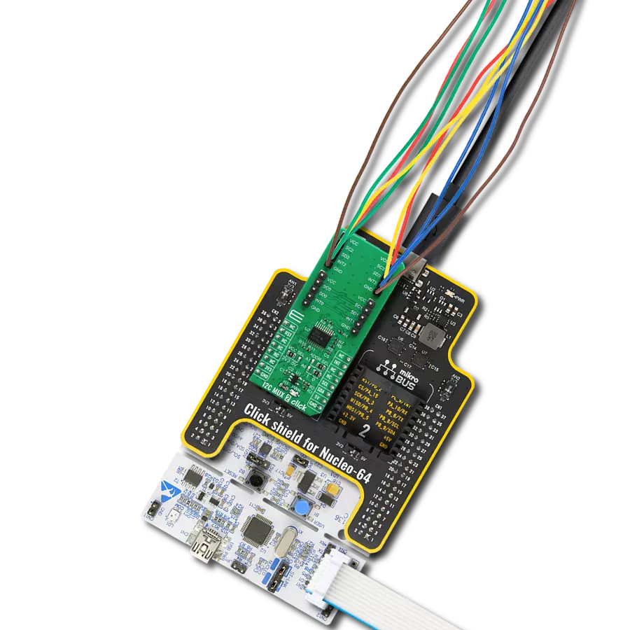
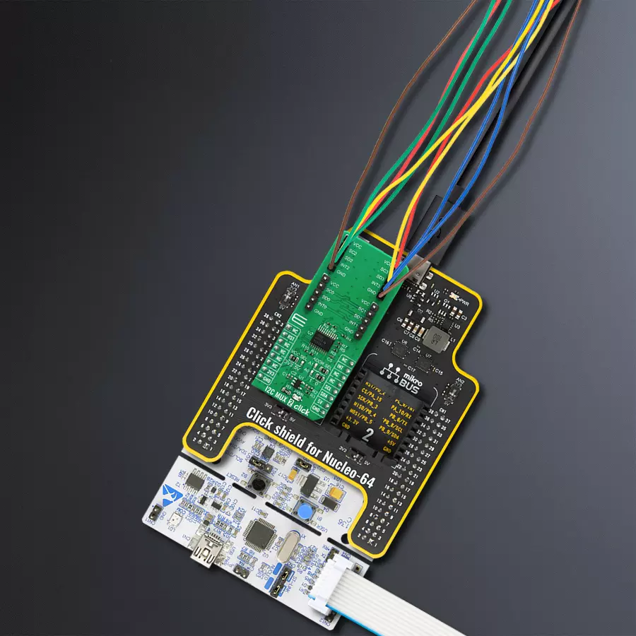
Start by selecting your development board and Click board™. Begin with the Nucleo-64 with STM32F091RC MCU as your development board.


Track your results in real time
Application Output
1. Application Output - In Debug mode, the 'Application Output' window enables real-time data monitoring, offering direct insight into execution results. Ensure proper data display by configuring the environment correctly using the provided tutorial.

2. UART Terminal - Use the UART Terminal to monitor data transmission via a USB to UART converter, allowing direct communication between the Click board™ and your development system. Configure the baud rate and other serial settings according to your project's requirements to ensure proper functionality. For step-by-step setup instructions, refer to the provided tutorial.

3. Plot Output - The Plot feature offers a powerful way to visualize real-time sensor data, enabling trend analysis, debugging, and comparison of multiple data points. To set it up correctly, follow the provided tutorial, which includes a step-by-step example of using the Plot feature to display Click board™ readings. To use the Plot feature in your code, use the function: plot(*insert_graph_name*, variable_name);. This is a general format, and it is up to the user to replace 'insert_graph_name' with the actual graph name and 'variable_name' with the parameter to be displayed.

Software Support
Library Description
This library contains API for I2C MUX 2 Click driver.
Key functions:
i2cmux2_hw_reset- This function resets I2C MUX 2 click board by clearing the RST pin for 100msi2cmux2_set_channel- Function sets channel of the I2C MUX 2 click boardi2cmux2_generic_read- This function reads data from the desired register.
Open Source
Code example
The complete application code and a ready-to-use project are available through the NECTO Studio Package Manager for direct installation in the NECTO Studio. The application code can also be found on the MIKROE GitHub account.
/*!
 * \file
 * \brief I2cMux2 Click example
 *
 * # Description
 * This example demonstrates the use of the I2C MUX 2 Click board.
 *
 * The demo application is composed of two sections :
 *
 * ## Application Init
 * Initializes the driver, performs the device reset, and makes an initial log.
 *
 * ## Application Task
 * In this example, we read the device ID register of the connected Click boards.
 * Channel 0 : 6DOF IMU 11 Click [slave address: 0x0E; reg: 0x00; id val.: 0x2D],
 * Channel 1 : Altitude Click    [slave address: 0x60; reg: 0x0C; id val.: 0xC4],
 * Channel 2 : 6DOF IMU 9 Click  [slave address: 0x69; reg: 0x75; id val.: 0xA9],
 * Channel 3 : Compass 3 Click   [slave address: 0x30; reg: 0x2F; id val.: 0x0C].
 * All data logs write on USB UART changes every 2 sec.
 *
 * @note
 * Disable all unconnected channels from the example using ENABLE_CHANNEL_x macros
 * below to prevent the I2C bus from blocking waiting for a device response.
 *
 * \author MikroE Team
 *
 */
// ------------------------------------------------------------------- INCLUDES

#include "board.h"
#include "log.h"
#include "i2cmux2.h"

// ------------------------------------------------------------------ VARIABLES

// Comment out the following lines to exclude unconnected channels from the example
#define ENABLE_CHANNEL_0
#define ENABLE_CHANNEL_1
#define ENABLE_CHANNEL_2
#define ENABLE_CHANNEL_3

static i2cmux2_t i2cmux2;
static log_t logger;
static uint8_t rx_data;

// ------------------------------------------------------- ADDITIONAL FUNCTIONS

void display_log ( uint8_t sel_ch )
{
    switch ( sel_ch )
    {
        case I2CMUX2_CMD_SET_CH_0:
        {
            log_printf( &logger, "   0  |  " );
            break;
        }
        case I2CMUX2_CMD_SET_CH_1:
        {
            log_printf( &logger, "   1  |  " );
            break;
        }
        case I2CMUX2_CMD_SET_CH_2:
        {
            log_printf( &logger, "   2  |  " );
            break;
        }
        case I2CMUX2_CMD_SET_CH_3:
        {
            log_printf( &logger, "   3  |  " );
            break;
        }
        default:
            break;
    }
    log_printf( &logger, "0x%.2X", ( uint16_t ) rx_data );

    if ( i2cmux2_check_int( &i2cmux2 ) == I2CMUX2_INT_PIN_STATE_ACTIVE )
    {
        if ( i2cmux2_read_interrupt( &i2cmux2 ) & sel_ch  )
        {
            log_printf( &logger, "  |  ON \r\n" );
        }
        else
        {
            log_printf( &logger, "  | OFF \r\n" );
        }
    }
    else
    {
        log_printf( &logger, "  | OFF \r\n" );
    }
}

// ------------------------------------------------------ APPLICATION FUNCTIONS

void application_init ( void )
{
    log_cfg_t log_cfg;
    i2cmux2_cfg_t cfg;

    /**
     * Logger initialization.
     * Default baud rate: 115200
     * Default log level: LOG_LEVEL_DEBUG
     * @note If USB_UART_RX and USB_UART_TX
     * are defined as HAL_PIN_NC, you will
     * need to define them manually for log to work.
     * See @b LOG_MAP_USB_UART macro definition for detailed explanation.
     */
    LOG_MAP_USB_UART( log_cfg );
    log_init( &logger, &log_cfg );
    log_info( &logger, "---- Application Init ----" );

    //  Click initialization.
    i2cmux2_cfg_setup( &cfg );
    I2CMUX2_MAP_MIKROBUS( cfg, MIKROBUS_1 );
    i2cmux2_init( &i2cmux2, &cfg );

    Delay_ms ( 100 );
    log_printf( &logger, "I2C MUX 2 Click driver init\r\n");
    log_printf( &logger, "---------------------------------------\r\n");
    Delay_ms ( 100 );

    i2cmux2_hw_reset( &i2cmux2 );
    log_printf( &logger, "I2C MUX 2 Click HW reset\r\n");
    log_printf( &logger, "---------------------------------------\r\n");
    Delay_ms ( 100 );
}

void application_task ( void )
{
    log_printf( &logger, "  CH  |   ID   |  INT \r\n" );
    log_printf( &logger, "----------------------\r\n" );

#ifdef ENABLE_CHANNEL_0
    // SET CHANNEL 0: 6DOF IMU 11 Click
    i2cmux2_set_channel( &i2cmux2, I2CMUX2_CMD_SET_CH_0, 0x0E );
    Delay_ms ( 100 );
    i2cmux2_generic_read( &i2cmux2, 0x00, &rx_data, 1 );
    display_log( I2CMUX2_CMD_SET_CH_0 );
#endif

#ifdef ENABLE_CHANNEL_1
    // SET CHANNEL 1: Altitude Click
    i2cmux2_set_channel( &i2cmux2, I2CMUX2_CMD_SET_CH_1, 0x60 );
    Delay_ms ( 100 );
    i2cmux2_generic_read( &i2cmux2, 0x0C, &rx_data, 1 );
    display_log( I2CMUX2_CMD_SET_CH_1 );
#endif

#ifdef ENABLE_CHANNEL_2
    // SET CHANNEL 2: 6DOF IMU 9 Click
    i2cmux2_set_channel( &i2cmux2, I2CMUX2_CMD_SET_CH_2, 0x69 );
    Delay_ms ( 100 );
    i2cmux2_generic_read( &i2cmux2, 0x75, &rx_data, 1 );
    display_log( I2CMUX2_CMD_SET_CH_2 );
#endif

#ifdef ENABLE_CHANNEL_3
    // SET CHANNEL 3: Compass 3 Click
    i2cmux2_set_channel( &i2cmux2, I2CMUX2_CMD_SET_CH_3, 0x30 );
    Delay_ms ( 100 );
    i2cmux2_generic_read( &i2cmux2, 0x2F, &rx_data, 1 );
    display_log( I2CMUX2_CMD_SET_CH_3 );
#endif

    log_printf( &logger, "----------------------\r\n" );
    Delay_ms ( 1000 );
    Delay_ms ( 1000 );
}

int main ( void )
{
    /* Do not remove this line or clock might not be set correctly. */
    #ifdef PREINIT_SUPPORTED
    preinit();
    #endif

    application_init( );

    for ( ; ; )
    {
        application_task( );
    }

    return 0;
}


// ------------------------------------------------------------------------ END
Additional Support
Resources
Category:I2C


