Extends your I2C bus using the CAN-physical layer with LT3960 and STM32F091RC
I2C to CAN-physical transceiver

Published Feb 26, 2024
Click board™
I2C to CAN Click
Dev. board
Nucleo-64 with STM32F091RC MCU
Compiler
NECTO Studio
MCU
STM32F091RC
Engineered for resilience in challenging environments, this robust high-speed transceiver extends a single-master I2C bus at speeds up to 400kbps, utilizing the CAN-physical layer to ensure reliable communication even in harsh or noisy conditions
A
A
Hardware Overview
How does it work?
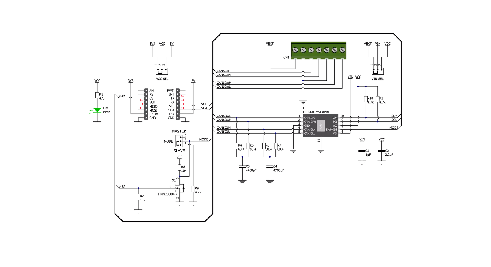
I2C to CAN Click is based on the LT3960, I2C to CAN-Physical transceiver used to send and receive I2C data up to 400kbps using the CAN-Physical layer for differential signaling over twisted pair connections from Analog Devices. Using two integrated CAN transceivers, the LT3960 creates a differential proxy for each single-ended I2C clock and data signal capable of crossing harsh or noisy environments across two twisted pairs. Each transceiver consists of a transmitter and receiver capable of quickly converting an I2C dominant signal into a differential dominant signal and vice versa. Also, it extends functionality in environments with high common-mode voltages due to electrical noise or local ground potential differences. I2C to CAN Click communicates with MCU using the standard I2C 2-Wire interface to
read data and configure settings, supporting Fast Mode operation with a clock frequency up to 400kHz. The LT3960 provides a mode selection feature selectable via jumper labeled as MODE, where the user can choose between the Master or Slave mode of operation. The SHD pin routed to the CS pin of the mikroBUS™ socket is used to put the LT3960 in a low-power Shutdown mode, disabling both the LDO and transceivers and allowing selection between Master and Slave modes when enabled. The selection between Master and Slave modes is performed by positioning the SMD jumper labeled as MODE to an appropriate position marked as SLV and MST. When a jumper is on the MST position, Master mode is selected, and the EN/MODE pin of the LT3960 is tied to a high logic state while floating
this pin, more precisely positioning the SMD jumper to an SLV position, allows the user to select Slave mode of operation. This Click board™ can operate with both 3.3V and 5V logic voltage levels selected via the VCC SEL jumper. It allows both 3.3V and 5V capable MCUs to use the I2C communication lines properly. Additionally, there is a possibility for the LT3960 power supply selection via jumper labeled as VIN SEL to supply the LT3960 from an external power supply terminal in the range from 4 to 60V or with VCC voltage levels from mikroBUS™ power rails. However, the Click board™ comes equipped with a library containing easy-to-use functions and an example code that can be used, as a reference, for further development.

Features overview
Development board
Nucleo-64 with STM32F091RC MCU offers a cost-effective and adaptable platform for developers to explore new ideas and prototype their designs. This board harnesses the versatility of the STM32 microcontroller, enabling users to select the optimal balance of performance and power consumption for their projects. It accommodates the STM32 microcontroller in the LQFP64 package and includes essential components such as a user LED, which doubles as an ARDUINO® signal, alongside user and reset push-buttons, and a 32.768kHz crystal oscillator for precise timing operations. Designed with expansion and flexibility in mind, the Nucleo-64 board features an ARDUINO® Uno V3 expansion connector and ST morpho extension pin
headers, granting complete access to the STM32's I/Os for comprehensive project integration. Power supply options are adaptable, supporting ST-LINK USB VBUS or external power sources, ensuring adaptability in various development environments. The board also has an on-board ST-LINK debugger/programmer with USB re-enumeration capability, simplifying the programming and debugging process. Moreover, the board is designed to simplify advanced development with its external SMPS for efficient Vcore logic supply, support for USB Device full speed or USB SNK/UFP full speed, and built-in cryptographic features, enhancing both the power efficiency and security of projects. Additional connectivity is
provided through dedicated connectors for external SMPS experimentation, a USB connector for the ST-LINK, and a MIPI® debug connector, expanding the possibilities for hardware interfacing and experimentation. Developers will find extensive support through comprehensive free software libraries and examples, courtesy of the STM32Cube MCU Package. This, combined with compatibility with a wide array of Integrated Development Environments (IDEs), including IAR Embedded Workbench®, MDK-ARM, and STM32CubeIDE, ensures a smooth and efficient development experience, allowing users to fully leverage the capabilities of the Nucleo-64 board in their projects.

Microcontroller Overview
MCU Card / MCU

Architecture
ARM Cortex-M0
MCU Memory (KB)
256
Silicon Vendor
STMicroelectronics
Pin count
64
RAM (Bytes)
32768
You complete me!
Accessories
Click Shield for Nucleo-64 comes equipped with two proprietary mikroBUS™ sockets, allowing all the Click board™ devices to be interfaced with the STM32 Nucleo-64 board with no effort. This way, Mikroe allows its users to add any functionality from our ever-growing range of Click boards™, such as WiFi, GSM, GPS, Bluetooth, ZigBee, environmental sensors, LEDs, speech recognition, motor control, movement sensors, and many more. More than 1537 Click boards™, which can be stacked and integrated, are at your disposal. The STM32 Nucleo-64 boards are based on the microcontrollers in 64-pin packages, a 32-bit MCU with an ARM Cortex M4 processor operating at 84MHz, 512Kb Flash, and 96KB SRAM, divided into two regions where the top section represents the ST-Link/V2 debugger and programmer while the bottom section of the board is an actual development board. These boards are controlled and powered conveniently through a USB connection to program and efficiently debug the Nucleo-64 board out of the box, with an additional USB cable connected to the USB mini port on the board. Most of the STM32 microcontroller pins are brought to the IO pins on the left and right edge of the board, which are then connected to two existing mikroBUS™ sockets. This Click Shield also has several switches that perform functions such as selecting the logic levels of analog signals on mikroBUS™ sockets and selecting logic voltage levels of the mikroBUS™ sockets themselves. Besides, the user is offered the possibility of using any Click board™ with the help of existing bidirectional level-shifting voltage translators, regardless of whether the Click board™ operates at a 3.3V or 5V logic voltage level. Once you connect the STM32 Nucleo-64 board with our Click Shield for Nucleo-64, you can access hundreds of Click boards™, working with 3.3V or 5V logic voltage levels.

Used MCU Pins
mikroBUS™ mapper
Take a closer look
Click board™ Schematic
Step by step
Project assembly
Start by selecting your development board and Click board™. Begin with the Nucleo-64 with STM32F091RC MCU as your development board.


Software Support
Library Description
This library contains API for I2C to CAN Click driver.
Key functions:
i2ctocan_set_slave_address- Set I2C Slave address functioni2ctocan_generic_write- I2C to CAN I2C writing functioni2ctocan_generic_read- I2C to CAN I2C reading function
Open Source
Code example
The complete application code and a ready-to-use project are available through the NECTO Studio Package Manager for direct installation in the NECTO Studio. The application code can also be found on the MIKROE GitHub account.
/*!
 * @file main.c
 * @brief I2cToCan Click example
 *
 * # Description
 * This library contains API for the I2C to CAN Click driver.
 * This demo application shows an example of an I2C CAN Click
 * wired to the VAV Press Click for reading
 * differential pressure and temperature measurement.
 *
 * The demo application is composed of two sections :
 *
 * ## Application Init
 * Initialization of I2C module and log UART.
 * After driver initialization and default settings,
 * the app set VAV Press Click I2C slave address ( 0x5C )
 * and enable device.
 *
 * ## Application Task
 * This is an example that shows the use of an I2C to CAN Click board™.
 * Logs pressure difference [ Pa ] and temperature [ degree Celsius ] values
 * of the VAV Press Click wired to the I2C to CAN Click board™.
 * Results are being sent to the Usart Terminal where you can track their changes.
 *
 * @note
 * void get_dif_press_and_temp ( void ) - Get differential pressure and temperature function.
 *
 * @author Nenad Filipovic
 *
 */

#include "board.h"
#include "log.h"
#include "i2ctocan.h"

#define I2CTOCAN_VAV_PRESS_DEV_ADDR                            0x5C
#define I2CTOCAN_VAV_PRESS_CMD_START_PRESSURE_CONVERSION       0x21
#define I2CTOCAN_VAV_PRESS_PRESS_SCALE_FACTOR                  1200
#define I2CTOCAN_VAV_PRESS_TEMP_SCALE_FACTOR                     72
#define I2CTOCAN_VAV_PRESS_READOUT_AT_KNOWN_TEMPERATURE         105
#define I2CTOCAN_VAV_PRESS_KNOWN_TEMPERATURE_C                   23.1

static i2ctocan_t i2ctocan;
static log_t logger;
static float diff_press;
static float temperature;

void get_dif_press_and_temp ( void ) {
    uint8_t rx_buf[ 4 ];
    int16_t readout_data;

    i2ctocan_generic_read( &i2ctocan, I2CTOCAN_VAV_PRESS_CMD_START_PRESSURE_CONVERSION, &rx_buf[ 0 ], 4 );

    readout_data = rx_buf[ 1 ];
    readout_data <<= 9;
    readout_data |= rx_buf[ 0 ];
    readout_data >>= 1;

    diff_press = ( float ) readout_data;
    diff_press /= I2CTOCAN_VAV_PRESS_PRESS_SCALE_FACTOR;

    readout_data = rx_buf[ 3 ];
    readout_data <<= 8;
    readout_data |= rx_buf[ 2 ];

    temperature = ( float ) readout_data;
    temperature -= I2CTOCAN_VAV_PRESS_READOUT_AT_KNOWN_TEMPERATURE;
    temperature /= I2CTOCAN_VAV_PRESS_TEMP_SCALE_FACTOR;
    temperature += I2CTOCAN_VAV_PRESS_KNOWN_TEMPERATURE_C;

}

void application_init ( void ) {
    log_cfg_t log_cfg;            /**< Logger config object. */
    i2ctocan_cfg_t i2ctocan_cfg;  /**< Click config object. */

    /**
     * Logger initialization.
     * Default baud rate: 115200
     * Default log level: LOG_LEVEL_DEBUG
     * @note If USB_UART_RX and USB_UART_TX
     * are defined as HAL_PIN_NC, you will
     * need to define them manually for log to work.
     * See @b LOG_MAP_USB_UART macro definition for detailed explanation.
     */
    LOG_MAP_USB_UART( log_cfg );
    log_init( &logger, &log_cfg );
    log_printf( &logger, "\r\n" );
    log_info( &logger, " Application Init " );

    // Click initialization.

    i2ctocan_cfg_setup( &i2ctocan_cfg );
    I2CTOCAN_MAP_MIKROBUS( i2ctocan_cfg, MIKROBUS_1 );
    err_t init_flag = i2ctocan_init( &i2ctocan, &i2ctocan_cfg );
    if ( init_flag == I2C_MASTER_ERROR ) {
        log_error( &logger, " Application Init Error. " );
        log_info( &logger, " Please, run program again... " );

        for ( ; ; );
    }

    i2ctocan_default_cfg ( &i2ctocan );
    log_info( &logger, " Application Task " );
    Delay_ms ( 100 );

    log_printf( &logger, "--------------------------------\r\n" );
    log_printf( &logger, "     Set I2C Slave Address      \r\n" );
    i2ctocan_set_slave_address ( &i2ctocan, I2CTOCAN_VAV_PRESS_DEV_ADDR );
    Delay_ms ( 100 );

    log_printf( &logger, "--------------------------------\r\n" );
    log_printf( &logger, "          Enable Device         \r\n" );
    log_printf( &logger, "--------------------------------\r\n" );
    i2ctocan_enable_device( &i2ctocan );
    Delay_ms ( 100 );
}

void application_task ( void ) {
    get_dif_press_and_temp( );

    log_printf( &logger, " Diff. Pressure    : %.4f Pa\r\n", diff_press );
    log_printf( &logger, " Temperature       : %.4f C\r\n", temperature );
    log_printf( &logger, "--------------------------------\r\n" );
    Delay_ms ( 1000 );
    Delay_ms ( 1000 );
}

int main ( void )
{
    /* Do not remove this line or clock might not be set correctly. */
    #ifdef PREINIT_SUPPORTED
    preinit();
    #endif

    application_init( );

    for ( ; ; )
    {
        application_task( );
    }

    return 0;
}

// ------------------------------------------------------------------------ END
Additional Support
Resources
Category:CAN


