Ensure a secure user experience with ADPD1080 and STM32L073RZ
Contactless recognition is not just a feature; it's our focus.

Published Feb 26, 2024
Click board™
IR Gesture 3 Click
Dev. board
Nucleo-64 with STM32L073RZ MCU
Compiler
NECTO Studio
MCU
STM32L073RZ
Experience the next level of interaction where your presence is all that's needed for seamless and secure recognition.
A
A
Hardware Overview
How does it work?
IR Gesture 3 Click is based on the ADPD1080, a photometric front-end from Analog Devices. It is a multifunction photometric front-end with fully integrated AFE, ADC, LED drivers, and timing core that enables ambient light rejection capability without photodiode optical filters. The drivers can deliver 370mA of peak current for LED, with flexible, multiple, and short LED pulses per optical sample. Its 14-bit ADC and 20-bit burst accumulator enable up to 20 bits per sample period, with sampling frequency ranging from 0.122Hz to 2700Hz. The ADPD1080 operates as a complete optical transceiver stimulating the SFH4249, a high-power infrared emitter from ams OSRAM, as a light source that works at 940nm and has a short switching time. The front-end IC then measures the return in the analog block through the separate current inputs, storing the results in discrete data locations. This data can be read by the host MCU. The ADPD1080 has a 1.8V analog/digital core; for this purpose, IR Gesture 3 Click uses the BH18PB1WHFV, a CMOS LDO regulator from Rohm Semiconductor. As current inputs, the ADPD1080 uses the ADPD2140, an
infrared light angle sensor from Analog Devices. It consists of a silicone P-type, intrinsic, N-type photodiode that provides a linear measurement of incident infrared light angle in four separate channels. The 2-axis light angle measurement is available in both x and y directions, where the resulting quantities are ratios related to angles through a constant term. The ADPD1080 front-end is connected with the ADPD2140 angle sensor via its four photodiode current inputs and a common photodiode cathode bias. The photodiode current inputs get analog data over the ADPD2140 analog outputs. While in State Machine operation, the ADPD1080 can operate in Standby, program, and Normal modes. The Normal mode follows a specific pattern set up by a state machine. The pattern consists of LED pulse and sample, intersample averaging, data read, and repeat. The LED pulse and sample pattern allow each data sample to be constructed from the user-configurable sum of pulses (1-255). The intersample averaging pattern samples in an average of 2 to 128 samples in powers of 2. With gesture recognition, a user interface can detect
hand movements and patterns and translate them into commands. It should consist of three basic functions. The first is the ability to detect a gesture's beginning and end, thus identifying what part of the gesture makes a command. The track of the hand movement during the gesture is the second part. The third is to identify the gesture based on the hand movement, its beginning and end. IR Gesture 3 Click uses a standard 2-Wire I2C interface to communicate with the host MCU, supporting up to 1Mbps data transfers. In addition to the I2C interface pins, the ADPD1080 uses two pins of the mikroBUS™ socket, IO0 and IO1 pins, for interrupts and various clocking options. For example, the external 32kHz clock signal can be provided over the IO1 pin of the mikroBUS™ socket. This Click board™ can be operated only with a 3.3V logic voltage level. The board must perform appropriate logic voltage level conversion before using MCUs with different logic levels. Also, it comes equipped with a library containing functions and an example code that can be used as a reference for further development.

Features overview
Development board
Nucleo-64 with STM32L073RZ MCU offers a cost-effective and adaptable platform for developers to explore new ideas and prototype their designs. This board harnesses the versatility of the STM32 microcontroller, enabling users to select the optimal balance of performance and power consumption for their projects. It accommodates the STM32 microcontroller in the LQFP64 package and includes essential components such as a user LED, which doubles as an ARDUINO® signal, alongside user and reset push-buttons, and a 32.768kHz crystal oscillator for precise timing operations. Designed with expansion and flexibility in mind, the Nucleo-64 board features an ARDUINO® Uno V3 expansion connector and ST morpho extension pin
headers, granting complete access to the STM32's I/Os for comprehensive project integration. Power supply options are adaptable, supporting ST-LINK USB VBUS or external power sources, ensuring adaptability in various development environments. The board also has an on-board ST-LINK debugger/programmer with USB re-enumeration capability, simplifying the programming and debugging process. Moreover, the board is designed to simplify advanced development with its external SMPS for efficient Vcore logic supply, support for USB Device full speed or USB SNK/UFP full speed, and built-in cryptographic features, enhancing both the power efficiency and security of projects. Additional connectivity is
provided through dedicated connectors for external SMPS experimentation, a USB connector for the ST-LINK, and a MIPI® debug connector, expanding the possibilities for hardware interfacing and experimentation. Developers will find extensive support through comprehensive free software libraries and examples, courtesy of the STM32Cube MCU Package. This, combined with compatibility with a wide array of Integrated Development Environments (IDEs), including IAR Embedded Workbench®, MDK-ARM, and STM32CubeIDE, ensures a smooth and efficient development experience, allowing users to fully leverage the capabilities of the Nucleo-64 board in their projects.

Microcontroller Overview
MCU Card / MCU

Architecture
ARM Cortex-M0
MCU Memory (KB)
192
Silicon Vendor
STMicroelectronics
Pin count
64
RAM (Bytes)
20480
You complete me!
Accessories
Click Shield for Nucleo-64 comes equipped with two proprietary mikroBUS™ sockets, allowing all the Click board™ devices to be interfaced with the STM32 Nucleo-64 board with no effort. This way, Mikroe allows its users to add any functionality from our ever-growing range of Click boards™, such as WiFi, GSM, GPS, Bluetooth, ZigBee, environmental sensors, LEDs, speech recognition, motor control, movement sensors, and many more. More than 1537 Click boards™, which can be stacked and integrated, are at your disposal. The STM32 Nucleo-64 boards are based on the microcontrollers in 64-pin packages, a 32-bit MCU with an ARM Cortex M4 processor operating at 84MHz, 512Kb Flash, and 96KB SRAM, divided into two regions where the top section represents the ST-Link/V2 debugger and programmer while the bottom section of the board is an actual development board. These boards are controlled and powered conveniently through a USB connection to program and efficiently debug the Nucleo-64 board out of the box, with an additional USB cable connected to the USB mini port on the board. Most of the STM32 microcontroller pins are brought to the IO pins on the left and right edge of the board, which are then connected to two existing mikroBUS™ sockets. This Click Shield also has several switches that perform functions such as selecting the logic levels of analog signals on mikroBUS™ sockets and selecting logic voltage levels of the mikroBUS™ sockets themselves. Besides, the user is offered the possibility of using any Click board™ with the help of existing bidirectional level-shifting voltage translators, regardless of whether the Click board™ operates at a 3.3V or 5V logic voltage level. Once you connect the STM32 Nucleo-64 board with our Click Shield for Nucleo-64, you can access hundreds of Click boards™, working with 3.3V or 5V logic voltage levels.

Used MCU Pins
mikroBUS™ mapper
Take a closer look
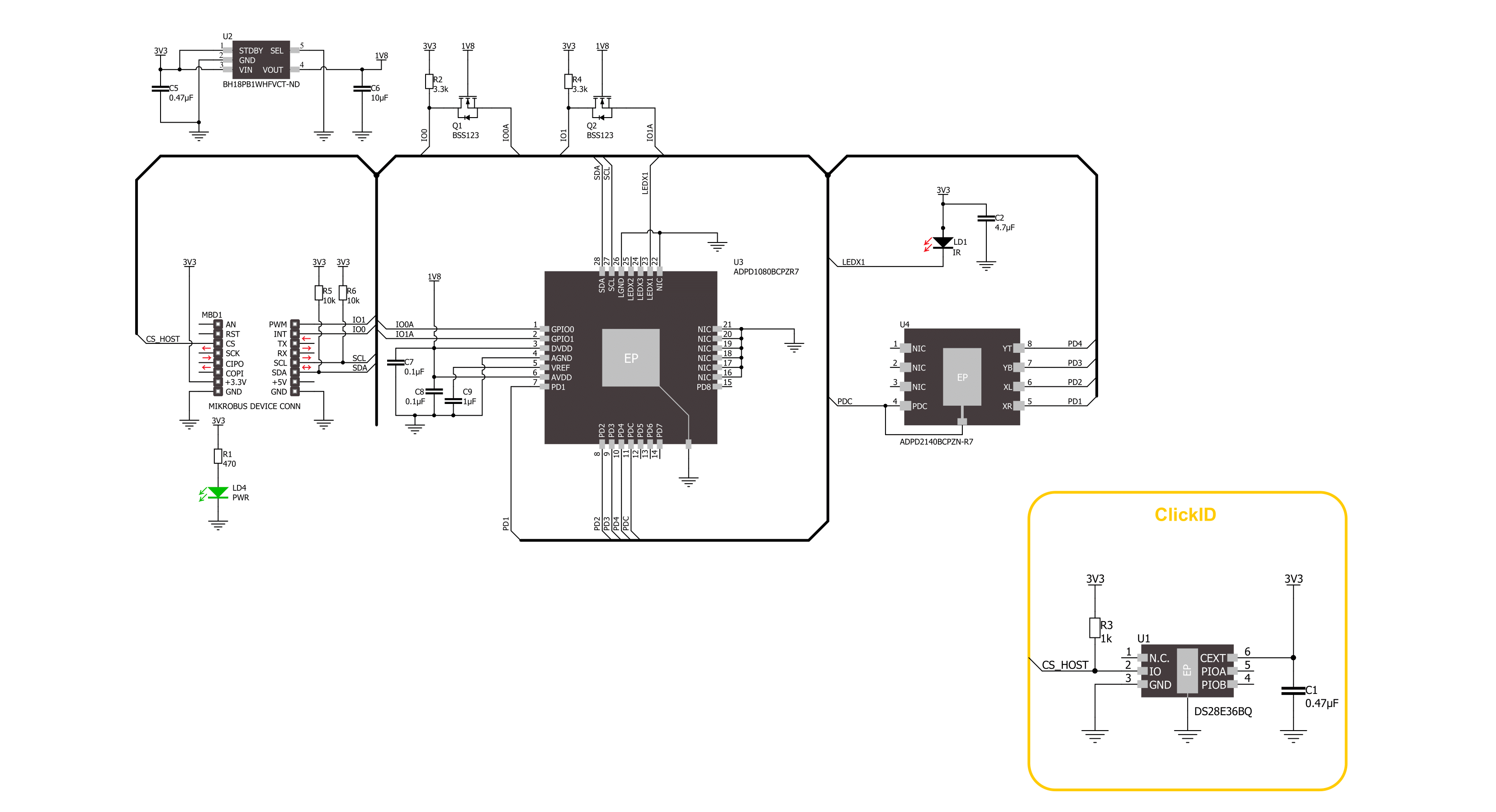
Click board™ Schematic
Step by step
Project assembly
Start by selecting your development board and Click board™. Begin with the Nucleo-64 with STM32L073RZ MCU as your development board.


Track your results in real time
Application Output
1. Application Output - In Debug mode, the 'Application Output' window enables real-time data monitoring, offering direct insight into execution results. Ensure proper data display by configuring the environment correctly using the provided tutorial.

2. UART Terminal - Use the UART Terminal to monitor data transmission via a USB to UART converter, allowing direct communication between the Click board™ and your development system. Configure the baud rate and other serial settings according to your project's requirements to ensure proper functionality. For step-by-step setup instructions, refer to the provided tutorial.

3. Plot Output - The Plot feature offers a powerful way to visualize real-time sensor data, enabling trend analysis, debugging, and comparison of multiple data points. To set it up correctly, follow the provided tutorial, which includes a step-by-step example of using the Plot feature to display Click board™ readings. To use the Plot feature in your code, use the function: plot(*insert_graph_name*, variable_name);. This is a general format, and it is up to the user to replace 'insert_graph_name' with the actual graph name and 'variable_name' with the parameter to be displayed.

Software Support
Library Description
This library contains API for IR Gesture 3 Click driver.
Key functions:
irgesture3_set_mode- This function sets the device operating mode.irgesture3_set_adc_fsample- This function sets the sample frequency of the device.irgesture3_get_gesture- This function waits up to IRGESTURE3_MAX_NUM_SAMPLES for an object to be detected and then calculates its gesture.
Open Source
Code example
The complete application code and a ready-to-use project are available through the NECTO Studio Package Manager for direct installation in the NECTO Studio. The application code can also be found on the MIKROE GitHub account.
/*!
 * @file main.c
 * @brief IR Gesture 3 Click example
 *
 * # Description
 * This example demonstrates the use of IR Gesture 3 Click board by processing
 * the incoming gestures and displaying them on the USB UART.
 *
 * The demo application is composed of two sections :
 *
 * ## Application Init
 * Initializes the driver and performs the Click default configuration.
 *
 * ## Application Task
 * Reads and processes all the incoming gestures and displays them on the USB UART.
 *
 * @author Stefan Filipovic
 *
 */

#include "board.h"
#include "log.h"
#include "irgesture3.h"

static irgesture3_t irgesture3;
static log_t logger;

void application_init ( void )
{
    log_cfg_t log_cfg;  /**< Logger config object. */
    irgesture3_cfg_t irgesture3_cfg;  /**< Click config object. */

    /**
     * Logger initialization.
     * Default baud rate: 115200
     * Default log level: LOG_LEVEL_DEBUG
     * @note If USB_UART_RX and USB_UART_TX
     * are defined as HAL_PIN_NC, you will
     * need to define them manually for log to work.
     * See @b LOG_MAP_USB_UART macro definition for detailed explanation.
     */
    LOG_MAP_USB_UART( log_cfg );
    log_init( &logger, &log_cfg );
    log_info( &logger, " Application Init " );

    // Click initialization.
    irgesture3_cfg_setup( &irgesture3_cfg );
    IRGESTURE3_MAP_MIKROBUS( irgesture3_cfg, MIKROBUS_1 );
    if ( I2C_MASTER_ERROR == irgesture3_init( &irgesture3, &irgesture3_cfg ) )
    {
        log_error( &logger, " Communication init." );
        for ( ; ; );
    }

    if ( IRGESTURE3_ERROR == irgesture3_default_cfg ( &irgesture3 ) )
    {
        log_error( &logger, " Default configuration." );
        for ( ; ; );
    }

    log_info( &logger, " Application Task " );
}

void application_task ( void )
{
    uint8_t gesture = 0;
    if ( IRGESTURE3_OK == irgesture3_get_gesture ( &irgesture3, &gesture ) )
    {
        log_printf( &logger, "\r\n Gesture: " );
        switch ( gesture )
        {
            case IRGESTURE3_GESTURE_CLICK:
            {
                log_printf( &logger, "CLICK\r\n" );
                break;
            }
            case IRGESTURE3_GESTURE_SWIPE_UP:
            {
                log_printf( &logger, "SWIPE UP\r\n" );
                break;
            }
            case IRGESTURE3_GESTURE_SWIPE_DOWN:
            {
                log_printf( &logger, "SWIPE DOWN\r\n" );
                break;
            }
            case IRGESTURE3_GESTURE_SWIPE_LEFT:
            {
                log_printf( &logger, "SWIPE LEFT\r\n" );
                break;
            }
            case IRGESTURE3_GESTURE_SWIPE_RIGHT:
            {
                log_printf( &logger, "SWIPE RIGHT\r\n" );
                break;
            }
            default:
            {
                log_printf( &logger, "UNKNOWN\r\n" );
                break;
            }
        }
    }
    else
    {
        log_printf( &logger, "\r\n No gesture detected!\r\n" );
    }
}

int main ( void )
{
    /* Do not remove this line or clock might not be set correctly. */
    #ifdef PREINIT_SUPPORTED
    preinit();
    #endif

    application_init( );

    for ( ; ; )
    {
        application_task( );
    }

    return 0;
}

// ------------------------------------------------------------------------ END
Additional Support
Resources
Category:Motion


