Establish long-distance wireless transmission with RFM75 and STM32F446RE
Stay connected without the hassle

Published Oct 08, 2024
Click board™
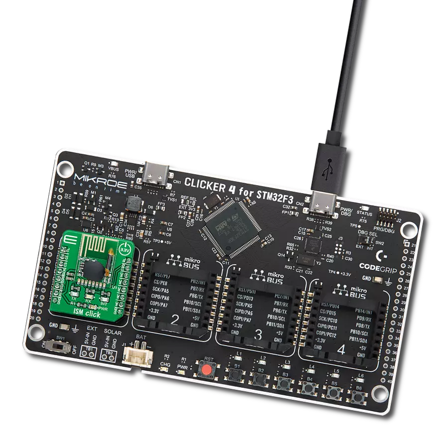
ISM Click
Dev. board
Nucleo 64 with STM32F446RE MCU
Compiler
NECTO Studio
MCU
STM32F446RE
Unleash the potential of your solution and get efficient, fast, and reliable wireless communication
A
A
Hardware Overview
How does it work?
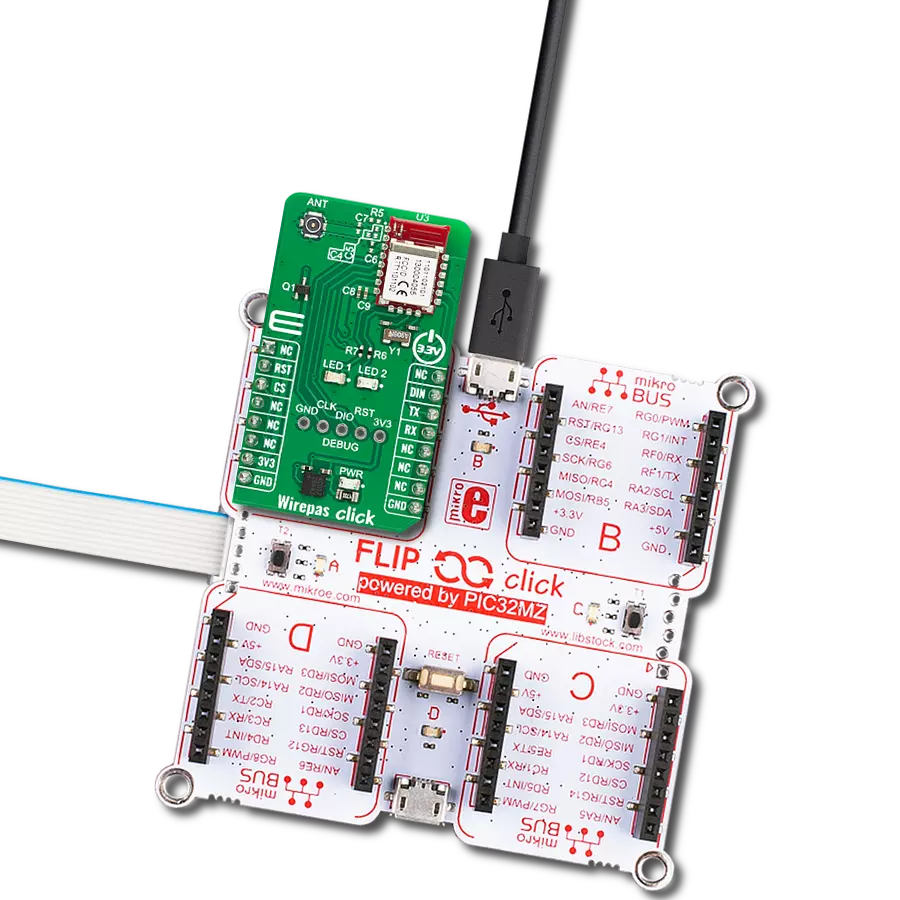
ISM Click is based on the RFM75, a low-power, high-performance 2.4GHz GFSK transceiver operating in the worldwide ISM frequency band from 2400MHz to 2527MHz from RF Solutions. The RFM75 operates in TDD mode, either as a transmitter or as a receiver. Burst mode transmission and up to 2Mbps air data rate make it suitable for ultra-low power consumption applications. The embedded packet processing engines enable their entire operation with a simple MCU as a radio system. Auto re-transmission and auto acknowledge giving reliable link without any MCU interference. A transmitter and receiver must be programmed with the same RF channel frequency to communicate, supporting a programmable air
data rate of 250Kbps, 1Mbps, or 2Mbps. The RF channel frequency determines the center of the channel used by RFM75. The RF_CH register, in register bank 0, sets the frequency according to the following formula F0= 2400 + RF_CH (MHz), where the resolution of the RF channel frequency is 1MHz. ISM Click communicates with MCU using the standard SPI serial interface that operates at clock rates up to 8 MHz. In power-down mode, RFM75 is in Sleep mode with minimal current consumption. The SPI interface is still active in this mode, and all register values are available by the SPI interface. This Click board™ also has a yellow LED indicator routed on the INT pin of the mikroBUS™ socket (provide the user with feedback after
a successfully received package) and a chip-enable function routed on the RST pin of the mikroBUS™ which activates TX or RX mode of the RFM75. Besides, it also has two additional LED indicators, a red and blue LED routed on the AN and PWM pins of the mikroBUS™ socket. The user can use it for visual indication when sending or receiving data. This Click board™ can only be operated with a 3.3V logic voltage level. The board must perform appropriate logic voltage level conversion before using MCUs with different logic levels. However, the Click board™ comes equipped with a library containing functions and an example code that can be used as a reference for further development.


Features overview
Development board
Nucleo-64 with STM32F446RE MCU offers a cost-effective and adaptable platform for developers to explore new ideas and prototype their designs. This board harnesses the versatility of the STM32 microcontroller, enabling users to select the optimal balance of performance and power consumption for their projects. It accommodates the STM32 microcontroller in the LQFP64 package and includes essential components such as a user LED, which doubles as an ARDUINO® signal, alongside user and reset push-buttons, and a 32.768kHz crystal oscillator for precise timing operations. Designed with expansion and flexibility in mind, the Nucleo-64 board features an ARDUINO® Uno V3 expansion connector and ST morpho extension pin
headers, granting complete access to the STM32's I/Os for comprehensive project integration. Power supply options are adaptable, supporting ST-LINK USB VBUS or external power sources, ensuring adaptability in various development environments. The board also has an on-board ST-LINK debugger/programmer with USB re-enumeration capability, simplifying the programming and debugging process. Moreover, the board is designed to simplify advanced development with its external SMPS for efficient Vcore logic supply, support for USB Device full speed or USB SNK/UFP full speed, and built-in cryptographic features, enhancing both the power efficiency and security of projects. Additional connectivity is
provided through dedicated connectors for external SMPS experimentation, a USB connector for the ST-LINK, and a MIPI® debug connector, expanding the possibilities for hardware interfacing and experimentation. Developers will find extensive support through comprehensive free software libraries and examples, courtesy of the STM32Cube MCU Package. This, combined with compatibility with a wide array of Integrated Development Environments (IDEs), including IAR Embedded Workbench®, MDK-ARM, and STM32CubeIDE, ensures a smooth and efficient development experience, allowing users to fully leverage the capabilities of the Nucleo-64 board in their projects.

Microcontroller Overview
MCU Card / MCU

Architecture
ARM Cortex-M4
MCU Memory (KB)
512
Silicon Vendor
STMicroelectronics
Pin count
64
RAM (Bytes)
131072
You complete me!
Accessories
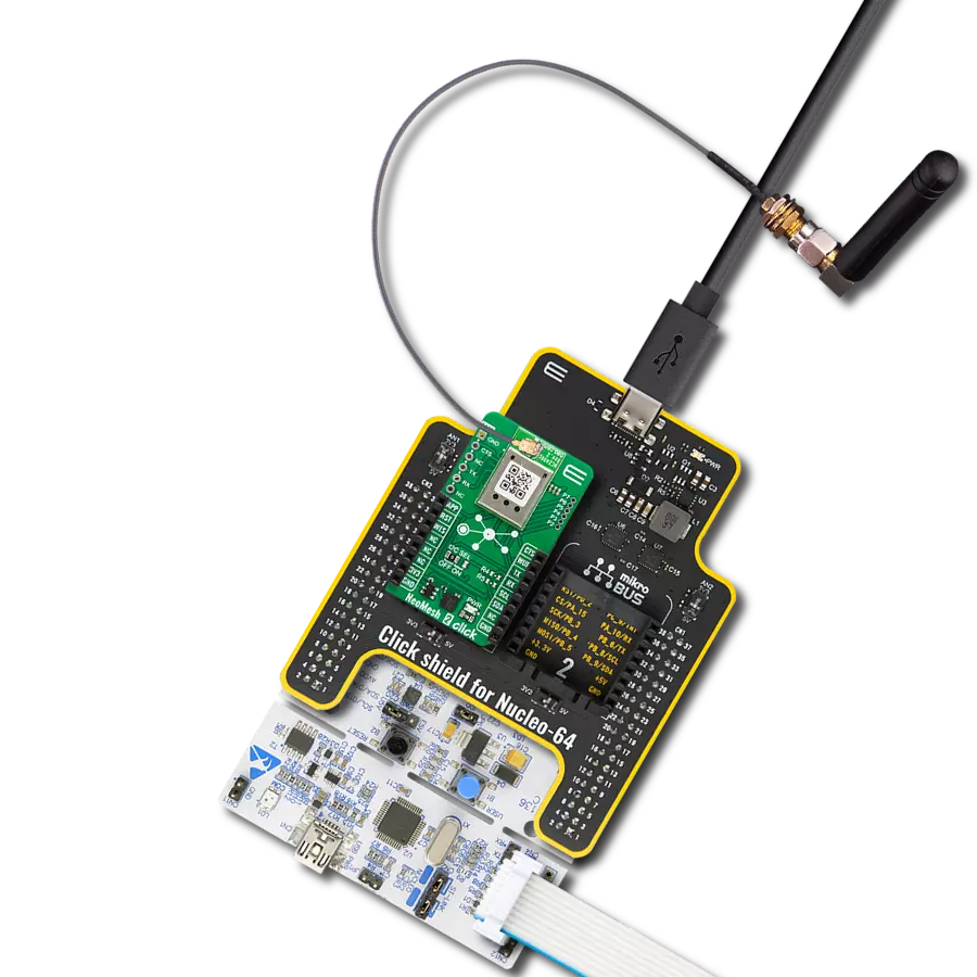
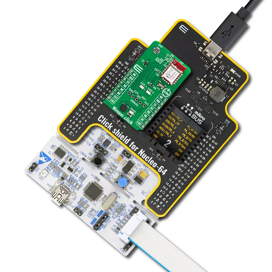
Click Shield for Nucleo-64 comes equipped with two proprietary mikroBUS™ sockets, allowing all the Click board™ devices to be interfaced with the STM32 Nucleo-64 board with no effort. This way, Mikroe allows its users to add any functionality from our ever-growing range of Click boards™, such as WiFi, GSM, GPS, Bluetooth, ZigBee, environmental sensors, LEDs, speech recognition, motor control, movement sensors, and many more. More than 1537 Click boards™, which can be stacked and integrated, are at your disposal. The STM32 Nucleo-64 boards are based on the microcontrollers in 64-pin packages, a 32-bit MCU with an ARM Cortex M4 processor operating at 84MHz, 512Kb Flash, and 96KB SRAM, divided into two regions where the top section represents the ST-Link/V2 debugger and programmer while the bottom section of the board is an actual development board. These boards are controlled and powered conveniently through a USB connection to program and efficiently debug the Nucleo-64 board out of the box, with an additional USB cable connected to the USB mini port on the board. Most of the STM32 microcontroller pins are brought to the IO pins on the left and right edge of the board, which are then connected to two existing mikroBUS™ sockets. This Click Shield also has several switches that perform functions such as selecting the logic levels of analog signals on mikroBUS™ sockets and selecting logic voltage levels of the mikroBUS™ sockets themselves. Besides, the user is offered the possibility of using any Click board™ with the help of existing bidirectional level-shifting voltage translators, regardless of whether the Click board™ operates at a 3.3V or 5V logic voltage level. Once you connect the STM32 Nucleo-64 board with our Click Shield for Nucleo-64, you can access hundreds of Click boards™, working with 3.3V or 5V logic voltage levels.

Used MCU Pins
mikroBUS™ mapper
Take a closer look
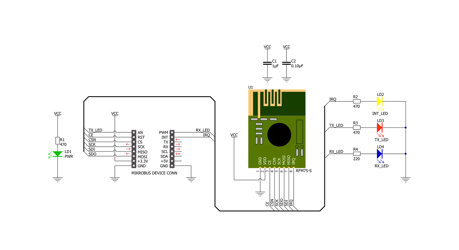
Click board™ Schematic
Step by step
Project assembly
Start by selecting your development board and Click board™. Begin with the Nucleo 64 with STM32F446RE MCU as your development board.


Software Support
Library Description
This library contains API for ISM Click driver.
Key functions:
ism_cfg_setup- Config Object Initialization function.ism_init- Initialization function.ism_default_cfg- Click Default Configuration function.
Open Source
Code example
The complete application code and a ready-to-use project are available through the NECTO Studio Package Manager for direct installation in the NECTO Studio. The application code can also be found on the MIKROE GitHub account.
/*!
 * @file main.c
 * @brief Ism Click example
 *
 * # Description
 * This library contains API for the ISM Click driver.
 * This example transmits/receives and processes data from ISM Clicks.
 *
 * The demo application is composed of two sections :
 *
 * ## Application Init
 * Initializes driver and performs the default configuration.
 *
 * ## Application Task
 * Transmitter/Receiver task depends on uncommented code.
 * Receiver logging each received byte to the UART for data logging,
 * while transmitter send messages every 1 second.
 *
 * @author Nenad Filipovic
 *
 */

#include "board.h"
#include "log.h"
#include "ism.h"

// Comment out the line below in order to switch the application mode to receiver
#define DEMO_APP_TRANSMITTER

static ism_t ism;
static log_t logger;

static uint8_t demo_message_1[ 9 ] = { 'M', 'i', 'k', 'r', 'o', 'E', 13, 10, 0 };
static uint8_t demo_message_2[ 12 ] = { 'I', 'S', 'M', ' ', 'C', 'l', 'i', 'c', 'k', 13, 10, 0 };

void application_init ( void )
{
    log_cfg_t log_cfg;  /**< Logger config object. */
    ism_cfg_t ism_cfg;  /**< Click config object. */

    /**
     * Logger initialization.
     * Default baud rate: 115200
     * Default log level: LOG_LEVEL_DEBUG
     * @note If USB_UART_RX and USB_UART_TX
     * are defined as HAL_PIN_NC, you will
     * need to define them manually for log to work.
     * See @b LOG_MAP_USB_UART macro definition for detailed explanation.
     */
    LOG_MAP_USB_UART( log_cfg );
    log_init( &logger, &log_cfg );
    log_info( &logger, " Application Init " );

    // Click initialization.
    ism_cfg_setup( &ism_cfg );
    ISM_MAP_MIKROBUS( ism_cfg, MIKROBUS_1 );
    if ( SPI_MASTER_ERROR == ism_init( &ism, &ism_cfg ) )
    {
        log_error( &logger, " Application Init Error. " );
        log_info( &logger, " Please, run program again... " );
        for ( ; ; );
    }

    ism_default_cfg ( &ism );
    Delay_ms ( 100 );

#ifdef DEMO_APP_TRANSMITTER
    ism_switch_tx_mode( &ism );
    log_printf( &logger, " Application Mode: Transmitter\r\n" );
#else
    ism_switch_rx_mode( &ism );
    log_printf( &logger, " Application Mode: Receiver\r\n" );
#endif
    log_info( &logger, " Application Task " );
}

void application_task ( void )
{
#ifdef DEMO_APP_TRANSMITTER
    ism_transmit_packet( &ism, ISM_CMD_W_TX_PAYLOAD_NOACK, demo_message_1, 9 );
    log_printf( &logger, "  Tx : %s", demo_message_1 );
    Delay_ms ( 1000 );

    ism_transmit_packet( &ism, ISM_CMD_W_TX_PAYLOAD_NOACK, demo_message_2, 12 );
    log_printf( &logger, "  Tx : %s", demo_message_2 );
    Delay_ms ( 1000 );
#else
    uint8_t rx_buf[ ISM_MAX_PACKET_LEN ] = { 0 };

    ism_receive_packet( &ism, &rx_buf[ 0 ] );

    if ( rx_buf[ 0 ] )
    {
        log_printf( &logger, "  Rx : %s", rx_buf );
    }
#endif
}

int main ( void )
{
    /* Do not remove this line or clock might not be set correctly. */
    #ifdef PREINIT_SUPPORTED
    preinit();
    #endif

    application_init( );

    for ( ; ; )
    {
        application_task( );
    }

    return 0;
}

// ------------------------------------------------------------------------ END
Additional Support
Resources
Category:2.4 GHz Transceivers