Enable seamless integration of smart lighting controls with TPS54200 and STM32F091RC
Lighting innovation at your fingertips
Published Feb 26, 2024
Click board™
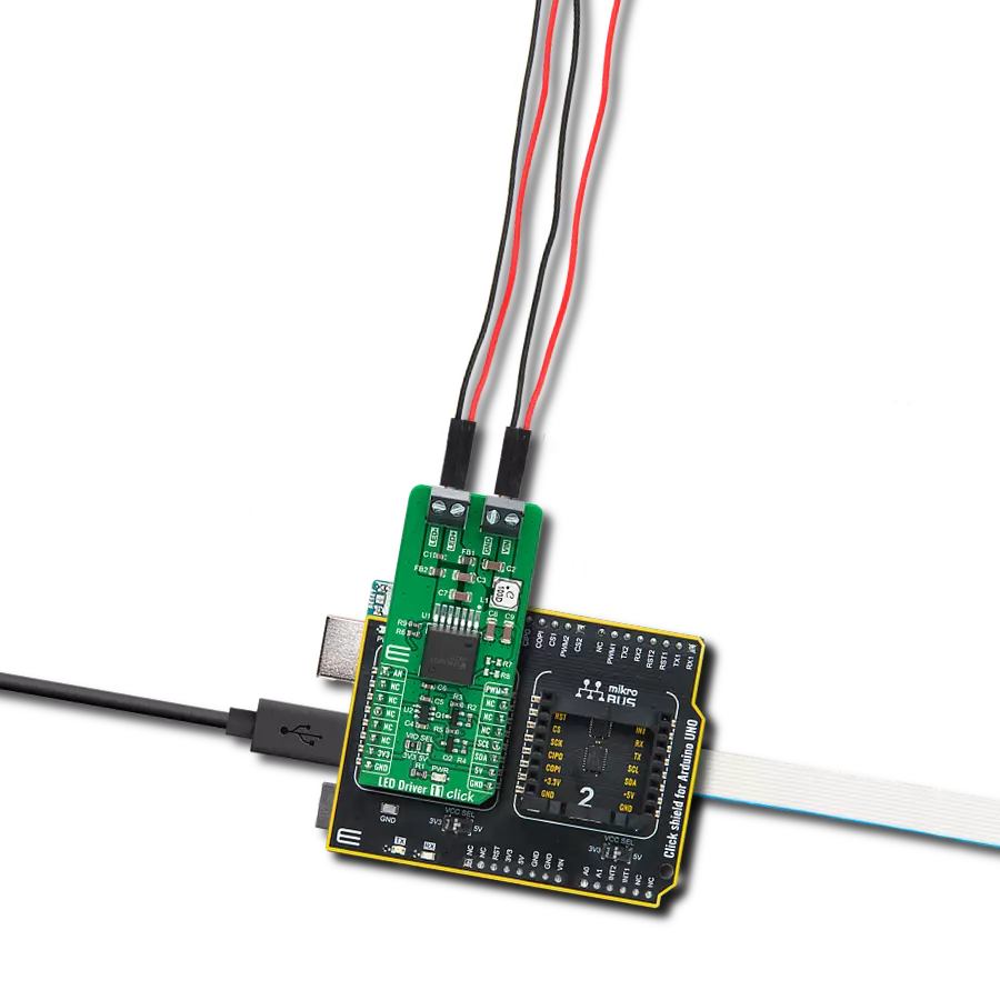
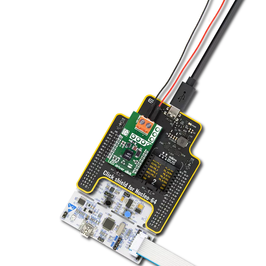
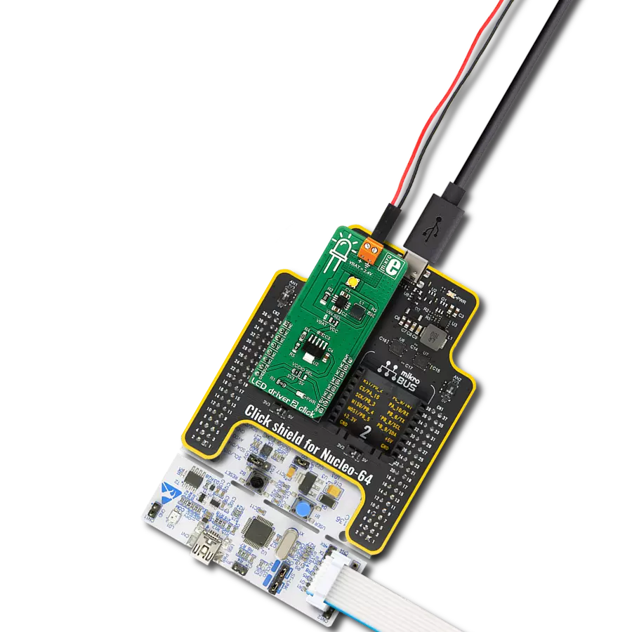
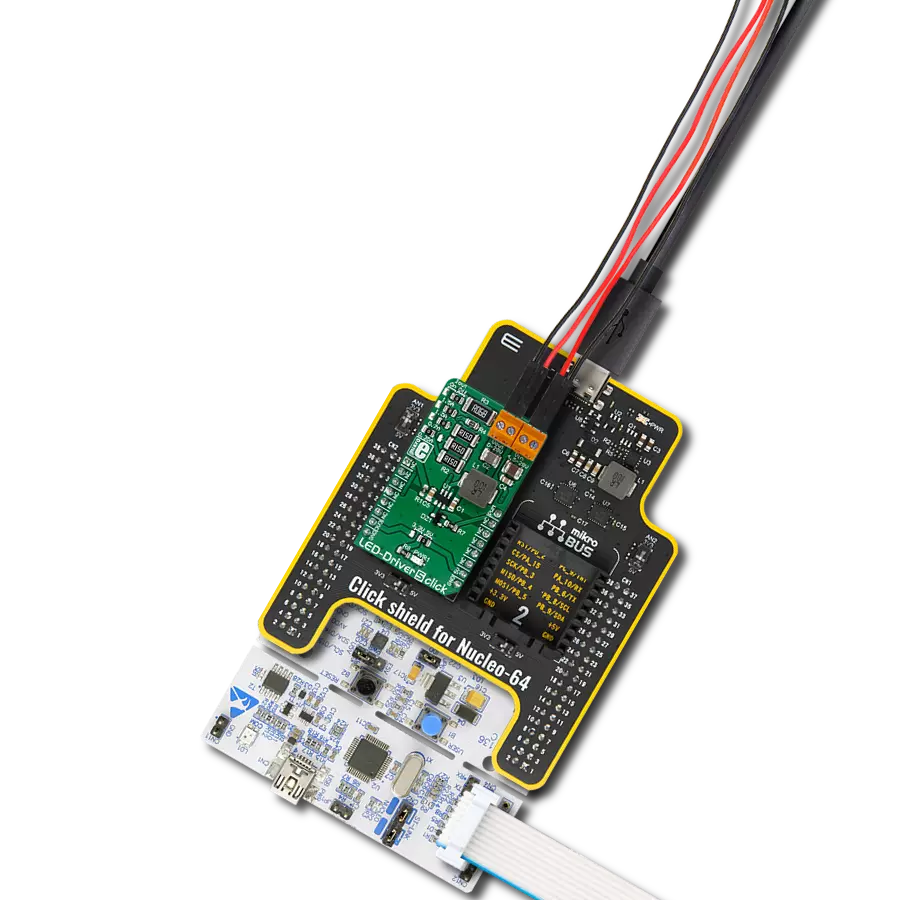
LED Driver 5 Click
Dev. board
Nucleo-64 with STM32F091RC MCU
Compiler
NECTO Studio
MCU
STM32F091RC
Ensure consistent and stable LED illumination in your electronic products, thanks to our precision LED driver technology
A
A
Hardware Overview
How does it work?
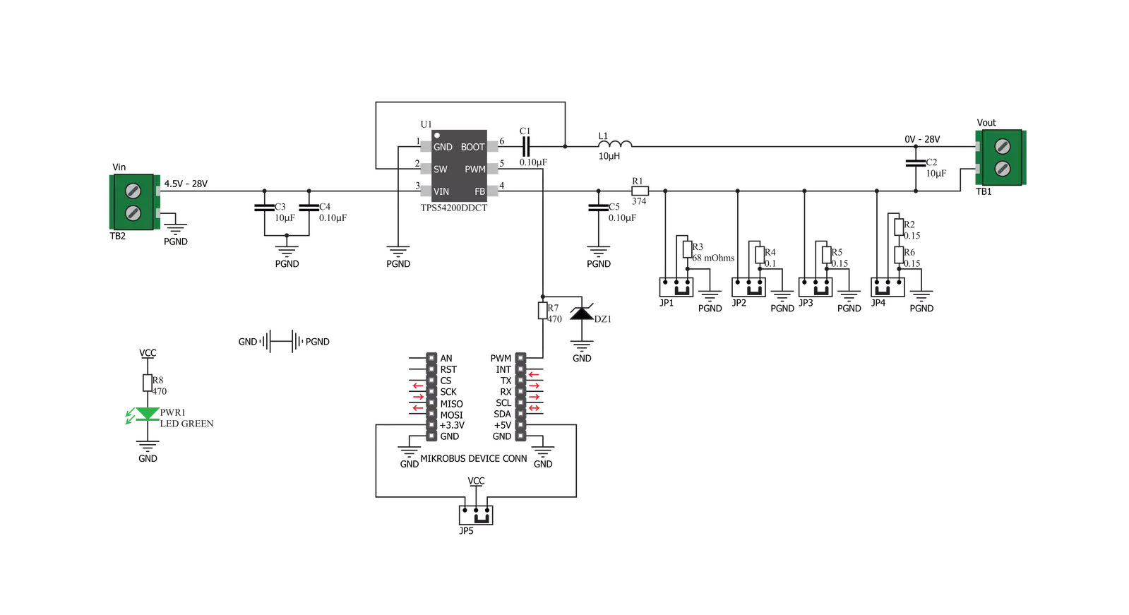
LED Driver 5 Click is based on the TPS54200, a synchronous buck converter designed to drive monochrome, color, and IR LED arrays made by Texas Instruments. The Click board™ is very flexible regarding the input voltage choice, allowing any voltage from 4.5V up to 28V. This is possible thanks to the TPS54200 driver IC, which integrates a buck converter IC and supports LED dimming by using the pulse width of the PWM signal on the control input. This IC has a mode selection logic circuitry used to select one of two dimming modes, depending on the incoming PWM control signal level. The PWM pin is used to control more than just one function. Besides choosing the dimming mode (analog or PWM), this pin is also used to turn the IC on or off. If the signal at the PWM pin rises above the threshold value (0.56V typically), the IC will be enabled. Keeping the voltage at the PWM pin lower than 0.56V for at least 40 ms will disable the IC. After the device is enabled, the magnitude of the PWM signal is detected and stored by an internal peak detector. The voltage of the peak detector is then compared with two threshold values, VADIM and VPDIM, after 300 µs. If the peak detector output exceeds 2.07V, analog dimming mode will be selected and locked. If the peak detector voltage ranges between 1V and 2.07V, the PWM dimming mode will be selected and locked. If the voltage is less than 1V, the detection process will be repeated
after 300 µs until one of two operating modes is selected and locked. Once locked, the dimming mode can only be changed by cycling the VIN voltage or re-enabling the IC. The PWM pin is routed to the PWM pin of the mikroBUS™, allowing it to be controlled by the host microcontroller (MCU). When the analog dimming mode is selected (the magnitude of the control PWM signal is above 2.06V during the boot-up sequence of the TPS54200), the internal reference voltage (VREF) is scaled down according to the duty cycle of the PWM signal applied to the PWM pin. The internal reference voltage for this mode is 200 mV at full scale (duty-cycle at 100%). As the duty cycle decreases, the reference voltage is scaled down to 1% of its value. This will also cause the current through the LED to be scaled, effectively dimming the LED. This type of dimming, where the LED intensity is dimmed to a low level invisible to the eye, is sometimes called deep-dimming. The PWM control signal at the PWM pin should stay within the range of 10 kHz to reduce the output voltage ripple. If the PWM dimming mode is selected (the magnitude of the control PWM signal is between 1V and 2.06V during the boot-up sequence of the TPS54200), the internal reference voltage is fixed at 100mA. In this mode, the LED dimming is performed using the PWM signal applied to the PWM pin, modulating the LED output. Holding the
internal reference voltage fixed, the LED at the output will only be switched ON or OFF, according to the duty cycle of the control PWM signal. The buck converter itself is a very feature-rich circuitry, a synchronous buck converter, operating at the fixed frequency of 600kHz. This offers an excellent size/efficiency ratio, keeping the footprint of the TPS54200 IC very small. Features such as the open LED or shorted LED detection, overvoltage and under-voltage protection, over-current and open loop protection, thermal shutdown, and soft start function that prevents the inrush current allow the Click board™ to be a very reliable and safe solution for driving high current LEDs or LED arrays. The Click board™ contains four SMD jumpers used to select the current through the LED array. They are grouped and labeled as IOUT. There are four settings: 0.35A, 0.7A, 1A, and 1.5A. Switching the current selection SMD jumper to the ON position will connect a respective sensing resistor (RS)to the circuit. Switching two SMD jumpers to the ON position simultaneously will cause them to form a parallel connection with their equivalent resistance. However, this is not recommended since almost all the resistor combinations will result in a value too low to be used (the LED current will be above 1.5A, thus triggering the protection circuit).

Features overview
Development board
Nucleo-64 with STM32F091RC MCU offers a cost-effective and adaptable platform for developers to explore new ideas and prototype their designs. This board harnesses the versatility of the STM32 microcontroller, enabling users to select the optimal balance of performance and power consumption for their projects. It accommodates the STM32 microcontroller in the LQFP64 package and includes essential components such as a user LED, which doubles as an ARDUINO® signal, alongside user and reset push-buttons, and a 32.768kHz crystal oscillator for precise timing operations. Designed with expansion and flexibility in mind, the Nucleo-64 board features an ARDUINO® Uno V3 expansion connector and ST morpho extension pin
headers, granting complete access to the STM32's I/Os for comprehensive project integration. Power supply options are adaptable, supporting ST-LINK USB VBUS or external power sources, ensuring adaptability in various development environments. The board also has an on-board ST-LINK debugger/programmer with USB re-enumeration capability, simplifying the programming and debugging process. Moreover, the board is designed to simplify advanced development with its external SMPS for efficient Vcore logic supply, support for USB Device full speed or USB SNK/UFP full speed, and built-in cryptographic features, enhancing both the power efficiency and security of projects. Additional connectivity is
provided through dedicated connectors for external SMPS experimentation, a USB connector for the ST-LINK, and a MIPI® debug connector, expanding the possibilities for hardware interfacing and experimentation. Developers will find extensive support through comprehensive free software libraries and examples, courtesy of the STM32Cube MCU Package. This, combined with compatibility with a wide array of Integrated Development Environments (IDEs), including IAR Embedded Workbench®, MDK-ARM, and STM32CubeIDE, ensures a smooth and efficient development experience, allowing users to fully leverage the capabilities of the Nucleo-64 board in their projects.

Microcontroller Overview
MCU Card / MCU

Architecture
ARM Cortex-M0
MCU Memory (KB)
256
Silicon Vendor
STMicroelectronics
Pin count
64
RAM (Bytes)
32768
You complete me!
Accessories
Click Shield for Nucleo-64 comes equipped with two proprietary mikroBUS™ sockets, allowing all the Click board™ devices to be interfaced with the STM32 Nucleo-64 board with no effort. This way, Mikroe allows its users to add any functionality from our ever-growing range of Click boards™, such as WiFi, GSM, GPS, Bluetooth, ZigBee, environmental sensors, LEDs, speech recognition, motor control, movement sensors, and many more. More than 1537 Click boards™, which can be stacked and integrated, are at your disposal. The STM32 Nucleo-64 boards are based on the microcontrollers in 64-pin packages, a 32-bit MCU with an ARM Cortex M4 processor operating at 84MHz, 512Kb Flash, and 96KB SRAM, divided into two regions where the top section represents the ST-Link/V2 debugger and programmer while the bottom section of the board is an actual development board. These boards are controlled and powered conveniently through a USB connection to program and efficiently debug the Nucleo-64 board out of the box, with an additional USB cable connected to the USB mini port on the board. Most of the STM32 microcontroller pins are brought to the IO pins on the left and right edge of the board, which are then connected to two existing mikroBUS™ sockets. This Click Shield also has several switches that perform functions such as selecting the logic levels of analog signals on mikroBUS™ sockets and selecting logic voltage levels of the mikroBUS™ sockets themselves. Besides, the user is offered the possibility of using any Click board™ with the help of existing bidirectional level-shifting voltage translators, regardless of whether the Click board™ operates at a 3.3V or 5V logic voltage level. Once you connect the STM32 Nucleo-64 board with our Click Shield for Nucleo-64, you can access hundreds of Click boards™, working with 3.3V or 5V logic voltage levels.

Used MCU Pins
mikroBUS™ mapper
Take a closer look
Click board™ Schematic
Step by step
Project assembly
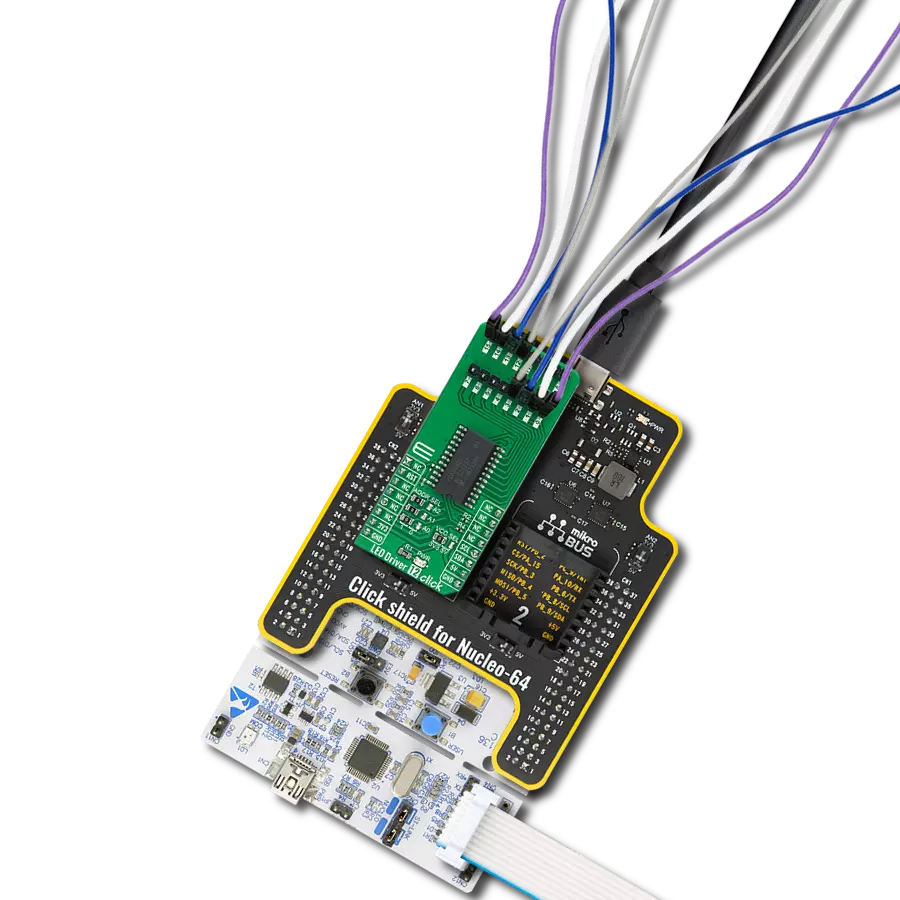
Start by selecting your development board and Click board™. Begin with the Nucleo-64 with STM32F091RC MCU as your development board.


Track your results in real time
Application Output
1. Application Output - In Debug mode, the 'Application Output' window enables real-time data monitoring, offering direct insight into execution results. Ensure proper data display by configuring the environment correctly using the provided tutorial.

2. UART Terminal - Use the UART Terminal to monitor data transmission via a USB to UART converter, allowing direct communication between the Click board™ and your development system. Configure the baud rate and other serial settings according to your project's requirements to ensure proper functionality. For step-by-step setup instructions, refer to the provided tutorial.

3. Plot Output - The Plot feature offers a powerful way to visualize real-time sensor data, enabling trend analysis, debugging, and comparison of multiple data points. To set it up correctly, follow the provided tutorial, which includes a step-by-step example of using the Plot feature to display Click board™ readings. To use the Plot feature in your code, use the function: plot(*insert_graph_name*, variable_name);. This is a general format, and it is up to the user to replace 'insert_graph_name' with the actual graph name and 'variable_name' with the parameter to be displayed.

Software Support
Library Description
This library contains API for LED Driver 5 Click driver.
Key functions:
leddriver5_set_duty_cycle- Generic sets PWM duty cycleleddriver5_pwm_stop- Stop PWM moduleleddriver5_pwm_start- Start PWM module
Open Source
Code example
The complete application code and a ready-to-use project are available through the NECTO Studio Package Manager for direct installation in the NECTO Studio. The application code can also be found on the MIKROE GitHub account.
/*!
 * @file
 * @brief LedDriver5 Click example
 *
 * # Description
 * The application is a capable of driving an array of high-power LEDs.
 *
 * The demo application is composed of two sections :
 *
 * ## Application Init
 * Initialization driver init and pwm init
 *
 * ## Application Task
 * This is an example that demonstrates the use of the LED Driver 5 Click board.
 * This example shows the automatic control of Led light intensity,
 * the first intensity of light is rising and then the intensity of light is falling.
 * Results are being sent to the Usart Terminal where you can track their changes.
 *
 *
 * @author Nikola Peric
 *
 */
// ------------------------------------------------------------------- INCLUDES

#include "board.h"
#include "log.h"
#include "leddriver5.h"

// ------------------------------------------------------------------ VARIABLES

static leddriver5_t leddriver5;
static log_t logger;

// ------------------------------------------------------ APPLICATION FUNCTIONS

void application_init ( void )
{
    log_cfg_t log_cfg;
    leddriver5_cfg_t cfg;

    /**
     * Logger initialization.
     * Default baud rate: 115200
     * Default log level: LOG_LEVEL_DEBUG
     * @note If USB_UART_RX and USB_UART_TX
     * are defined as HAL_PIN_NC, you will
     * need to define them manually for log to work.
     * See @b LOG_MAP_USB_UART macro definition for detailed explanation.
     */
    LOG_MAP_USB_UART( log_cfg );
    log_init( &logger, &log_cfg );
    log_info( &logger, "---- Application Init ----" );

    //  Click initialization.

    leddriver5_cfg_setup( &cfg );
    LEDDRIVER5_MAP_MIKROBUS( cfg, MIKROBUS_1 );
    leddriver5_init( &leddriver5, &cfg );

    leddriver5_pwm_start( &leddriver5 );
}

void application_task ( void )
{
    static int8_t duty_cnt = 1;
    static int8_t duty_inc = 1;
    float duty = duty_cnt / 10.0;

    leddriver5_set_duty_cycle( &leddriver5, duty );
    log_printf( &logger, "> Duty: %d%%\r\n", ( uint16_t )( duty_cnt * 10 ) );

    Delay_ms ( 500 );

    if ( 10 == duty_cnt )
    {
        duty_inc = -1;
    }
    else if ( 0 == duty_cnt )
    {
        duty_inc = 1;
    }
    duty_cnt += duty_inc;
}

int main ( void )
{
    /* Do not remove this line or clock might not be set correctly. */
    #ifdef PREINIT_SUPPORTED
    preinit();
    #endif

    application_init( );

    for ( ; ; )
    {
        application_task( );
    }

    return 0;
}


// ------------------------------------------------------------------------ END
Additional Support
Resources
Category:LED Drivers