Improve the aesthetics of your space with ALI781 and STM32L073RZ
Bright ideas start here

Published Feb 26, 2024
Click board™
LED Driver 6 Click
Dev. board
Nucleo-64 with STM32L073RZ MCU
Compiler
NECTO Studio
MCU
STM32L073RZ
Enable easy control and customization of LED-based features in your electronic gadgets with our flexible LED driver
A
A
Hardware Overview
How does it work?
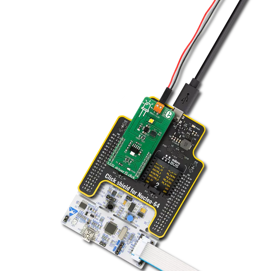
LED Driver 6 Click is based on the AL1781, a single-channel PWM dimmable linear LED driver by Diodes Incorporated. It is a constant-current driver, which can sink up to 1500mA. It has a low-side current sink, which allows LED strips or LED bulbs to be connected in the common-anode topology for increased effectiveness and power optimization. The constant current through the connected LED can be selected by an SMD jumper labeled as ILED between two values: 1A and 1.5A. The AL1781 IC can be operated with a PWM signal in the frequency range from 1kHz to 40kHz. Applying the PWM signal with a duty cycle of less than 4ms makes it possible to tune the light intensity of the connected LED light element. A LOW pulse width of more than 4ms will set the device into the low-power mode (suspend). The lowest light intensity that can be reached by applying the PWM frequency of 1kHz is 0.1%, while 40kHz allows the lowest brightness level of 4% of the full light intensity. A High PWM frequency allows for less visible flickering but simultaneously limits the lowest light intensity level. PWM1 and PWM2 pins of the AL1781 are routed to the mikroBUS™ PWM and CS pins and are labeled as PW1 and PW2. Adaptive Thermal Management (ATM) scheme is one of the key features of the AL1781. It can be used to optimize the power
consumption by adjusting the voltage of the external power supply unit (PSU): the excessive voltage applied to the connected LED will be dissipated as heat within the AL1781 IC. Therefore, the voltage level of the external PSU should be kept above the forward voltage of the connected LED plus minimum voltage headroom (VF + VLED_REG). The ATM injects current through the LEDPG pin of the AL1781. This current is converted to a voltage level, and it is sampled by the MCP3221, a low-power 12-bit A/D converter with an I2C interface, by Microchip. It has its I2C pins routed to the respective mikroBUS™ I2C pins, allowing the host MCU to read the LEDPG voltage and adjust the PSU voltage. Please note that if an external PSU with no external regulation is used, its voltage should stay within the mentioned range (VF of the connected LED element + VLEDx_REG as per AL1781 datasheet). However, the voltage should always stay below 30V. The AL1781 IC also integrates many protection features for increased reliability: undervoltage, open or short circuit at the output, and thermal protection. If any of these protections become activated, a fault event will be reported on a dedicated pin labeled FAULTB. This pin is routed to the mikroBUS™ INT pin and is asserted to a LOW logic level when a fault event occurs. Deep Dimming
Capability helps with power efficiency. Subjective perception of the light intensity differs from the measured light. For example, the light intensity of 10% (with respect to the applied duty cycle) is perceived as 32% of the full light intensity. Deep Dimming Capability helps with energy saving, providing an optimal light output. Deep Dimming down to 0.1% is possible with the AL1781 IC since it can be operated with a pulse width as low as 1µS while still providing good linearity. LED driver 6 Click is designed to use an external PSU and an MCU. The full potential of the LED driver 6 Click is achieved when combined with a dedicated ambient light sensing Click board™ such as Ambient 5 Click: by receiving information about the ambient light intensity from Ambient 5 Click, the MCU can generate PWM signal with respect to the required intensity tuning and send it to LED driver 6 Click to regulate the intensity of the ambient lighting. This Click board™ can be operated only with a 3.3V logic voltage level. The board must perform appropriate logic voltage level conversion before using MCUs with different logic levels. Also, it comes equipped with a library containing functions and an example code that can be used as a reference for further development.

Features overview
Development board
Nucleo-64 with STM32L073RZ MCU offers a cost-effective and adaptable platform for developers to explore new ideas and prototype their designs. This board harnesses the versatility of the STM32 microcontroller, enabling users to select the optimal balance of performance and power consumption for their projects. It accommodates the STM32 microcontroller in the LQFP64 package and includes essential components such as a user LED, which doubles as an ARDUINO® signal, alongside user and reset push-buttons, and a 32.768kHz crystal oscillator for precise timing operations. Designed with expansion and flexibility in mind, the Nucleo-64 board features an ARDUINO® Uno V3 expansion connector and ST morpho extension pin
headers, granting complete access to the STM32's I/Os for comprehensive project integration. Power supply options are adaptable, supporting ST-LINK USB VBUS or external power sources, ensuring adaptability in various development environments. The board also has an on-board ST-LINK debugger/programmer with USB re-enumeration capability, simplifying the programming and debugging process. Moreover, the board is designed to simplify advanced development with its external SMPS for efficient Vcore logic supply, support for USB Device full speed or USB SNK/UFP full speed, and built-in cryptographic features, enhancing both the power efficiency and security of projects. Additional connectivity is
provided through dedicated connectors for external SMPS experimentation, a USB connector for the ST-LINK, and a MIPI® debug connector, expanding the possibilities for hardware interfacing and experimentation. Developers will find extensive support through comprehensive free software libraries and examples, courtesy of the STM32Cube MCU Package. This, combined with compatibility with a wide array of Integrated Development Environments (IDEs), including IAR Embedded Workbench®, MDK-ARM, and STM32CubeIDE, ensures a smooth and efficient development experience, allowing users to fully leverage the capabilities of the Nucleo-64 board in their projects.

Microcontroller Overview
MCU Card / MCU

Architecture
ARM Cortex-M0
MCU Memory (KB)
192
Silicon Vendor
STMicroelectronics
Pin count
64
RAM (Bytes)
20480
You complete me!
Accessories
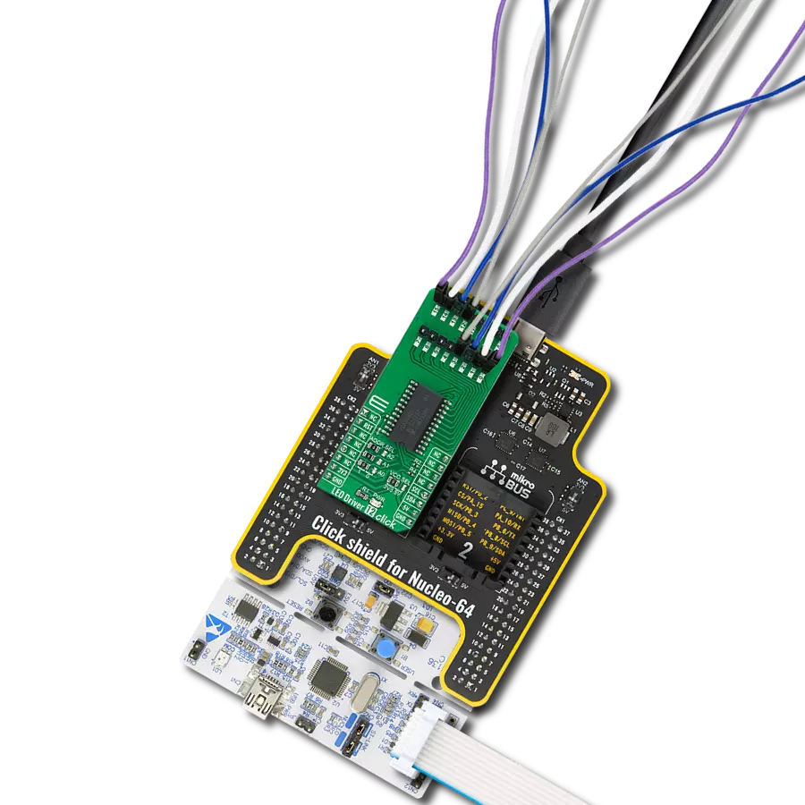
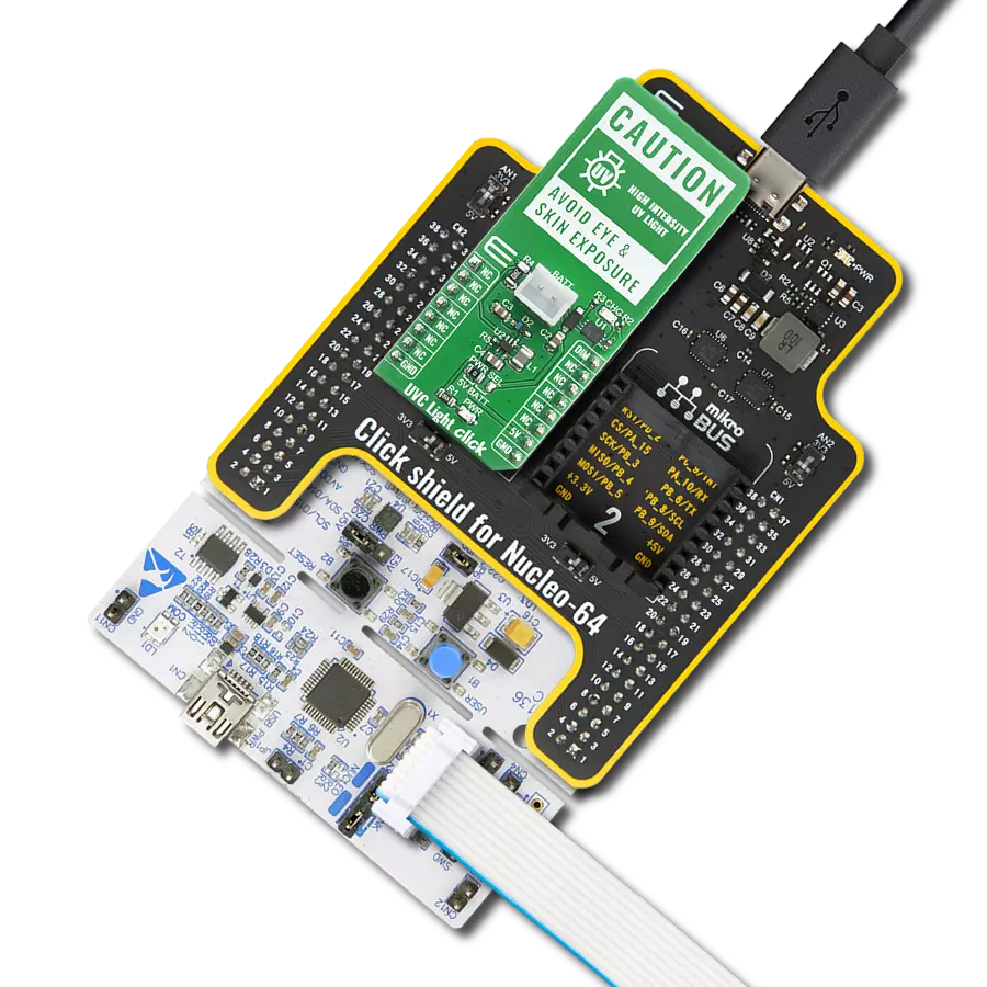
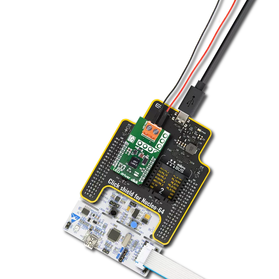
Click Shield for Nucleo-64 comes equipped with two proprietary mikroBUS™ sockets, allowing all the Click board™ devices to be interfaced with the STM32 Nucleo-64 board with no effort. This way, Mikroe allows its users to add any functionality from our ever-growing range of Click boards™, such as WiFi, GSM, GPS, Bluetooth, ZigBee, environmental sensors, LEDs, speech recognition, motor control, movement sensors, and many more. More than 1537 Click boards™, which can be stacked and integrated, are at your disposal. The STM32 Nucleo-64 boards are based on the microcontrollers in 64-pin packages, a 32-bit MCU with an ARM Cortex M4 processor operating at 84MHz, 512Kb Flash, and 96KB SRAM, divided into two regions where the top section represents the ST-Link/V2 debugger and programmer while the bottom section of the board is an actual development board. These boards are controlled and powered conveniently through a USB connection to program and efficiently debug the Nucleo-64 board out of the box, with an additional USB cable connected to the USB mini port on the board. Most of the STM32 microcontroller pins are brought to the IO pins on the left and right edge of the board, which are then connected to two existing mikroBUS™ sockets. This Click Shield also has several switches that perform functions such as selecting the logic levels of analog signals on mikroBUS™ sockets and selecting logic voltage levels of the mikroBUS™ sockets themselves. Besides, the user is offered the possibility of using any Click board™ with the help of existing bidirectional level-shifting voltage translators, regardless of whether the Click board™ operates at a 3.3V or 5V logic voltage level. Once you connect the STM32 Nucleo-64 board with our Click Shield for Nucleo-64, you can access hundreds of Click boards™, working with 3.3V or 5V logic voltage levels.

Used MCU Pins
mikroBUS™ mapper
Take a closer look
Click board™ Schematic

Step by step
Project assembly
Start by selecting your development board and Click board™. Begin with the Nucleo-64 with STM32L073RZ MCU as your development board.


Track your results in real time
Application Output
1. Application Output - In Debug mode, the 'Application Output' window enables real-time data monitoring, offering direct insight into execution results. Ensure proper data display by configuring the environment correctly using the provided tutorial.

2. UART Terminal - Use the UART Terminal to monitor data transmission via a USB to UART converter, allowing direct communication between the Click board™ and your development system. Configure the baud rate and other serial settings according to your project's requirements to ensure proper functionality. For step-by-step setup instructions, refer to the provided tutorial.

3. Plot Output - The Plot feature offers a powerful way to visualize real-time sensor data, enabling trend analysis, debugging, and comparison of multiple data points. To set it up correctly, follow the provided tutorial, which includes a step-by-step example of using the Plot feature to display Click board™ readings. To use the Plot feature in your code, use the function: plot(*insert_graph_name*, variable_name);. This is a general format, and it is up to the user to replace 'insert_graph_name' with the actual graph name and 'variable_name' with the parameter to be displayed.

Software Support
Library Description
This library contains API for LED Driver 6 Click driver.
Key functions:
leddriver6_set_duty_cycle- Generic sets PWM duty cycleleddriver6_pwm_stop- Stop PWM moduleleddriver6_pwm_start- Start PWM module.
Open Source
Code example
The complete application code and a ready-to-use project are available through the NECTO Studio Package Manager for direct installation in the NECTO Studio. The application code can also be found on the MIKROE GitHub account.
/*!
 * @file
 * @brief Leddriver6 Click example
 *
 * # Description
 * This application designed to be used in tunable Smart Connected Lighting applications.
 *
 * The demo application is composed of two sections :
 *
 * ## Application Init
 * Initializes I2C driver and PWM driver for the LED driver 6 control.
 *
 * ## Application Task
 * This is an example that demonstrates the use of the LED Driver 6 Click board.
 * This example shows the automatic control LED light intensity,
 * the first intensity of light is rising and then the intensity of light is falling.
 * Results are being sent to the Usart Terminal where you can track their changes.
 *
 * @author Nikola Peric
 *
 */

#include "board.h"
#include "log.h"
#include "leddriver6.h"

static leddriver6_t leddriver6;
static log_t logger;

void application_init ( void )
{
    log_cfg_t log_cfg;

    /**
     * Logger initialization.
     * Default baud rate: 115200
     * Default log level: LOG_LEVEL_DEBUG
     * @note If USB_UART_RX and USB_UART_TX
     * are defined as HAL_PIN_NC, you will
     * need to define them manually for log to work.
     * See @b LOG_MAP_USB_UART macro definition for detailed explanation.
     */
    LOG_MAP_USB_UART( log_cfg );
    log_init( &logger, &log_cfg );
    log_info( &logger, "---- Application Init... ----" );

    leddriver6_cfg_t leddriver6_cfg;

    //  Click initialization.

    leddriver6_cfg_setup( &leddriver6_cfg );
    LEDDRIVER6_MAP_MIKROBUS( leddriver6_cfg, MIKROBUS_1 );

    if ( leddriver6_init( &leddriver6, &leddriver6_cfg ) == LEDDRIVER6_INIT_ERROR )
    {
        log_info( &logger, "---- Application Init Error. ----" );
        log_info( &logger, "---- Please, run program again... ----" );

        for ( ; ; );
    }

    log_info( &logger, "---- Application Init Done. ----" );

    leddriver6_set_duty_cycle ( &leddriver6, 0.0 );
    if ( leddriver6_pwm_start( &leddriver6 ) == LEDDRIVER6_INIT_ERROR )
    {
        log_info( &logger, "---- PWM can't be started. ----" );
        log_info( &logger, "---- Please, run program again... ----" );

        for ( ; ; );
    }

    log_info( &logger, "---- PWM is started. ----" );
    log_info( &logger, "---- Application Task ----" );
    Delay_ms ( 500 );
}

void application_task ( void )
{
    static int8_t duty_cnt = 1;
    static int8_t duty_inc = 1;
    float duty = duty_cnt / 10.0;

    leddriver6_set_duty_cycle ( &leddriver6, duty );
    log_printf( &logger, "Duty: %d%%\r\n", ( uint16_t )( duty_cnt * 10 ) );
    Delay_ms ( 500 );

    if ( 10 == duty_cnt )
    {
        duty_inc = -1;
    }
    else if ( 0 == duty_cnt )
    {
        duty_inc = 1;
    }
    duty_cnt += duty_inc;
}

int main ( void )
{
    /* Do not remove this line or clock might not be set correctly. */
    #ifdef PREINIT_SUPPORTED
    preinit();
    #endif

    application_init( );

    for ( ; ; )
    {
        application_task( );
    }

    return 0;
}

// ------------------------------------------------------------------------ END
Additional Support
Resources
Category:LED Drivers