Reduce the input voltage to a desired output level with MAXM38643 and STM32F446RE
NanoPower buck solution with industry’s lowest IQ

Published Oct 08, 2024
Click board™
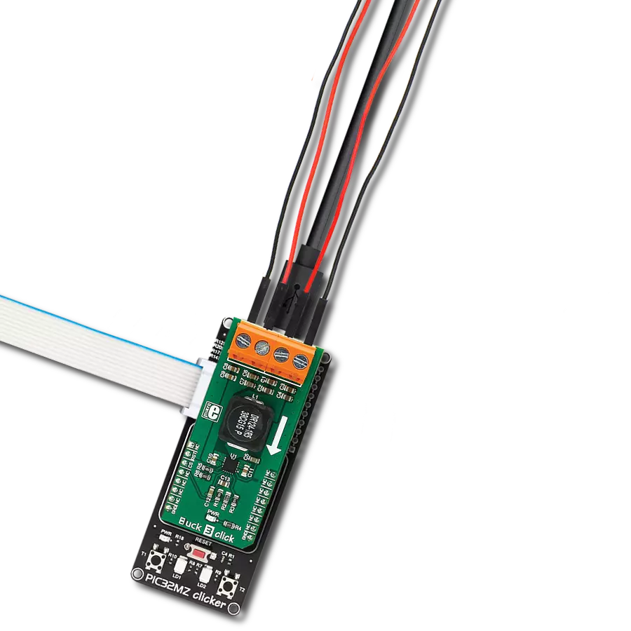
Buck 18 Click
Dev. board
Nucleo 64 with STM32F446RE MCU
Compiler
NECTO Studio
MCU
STM32F446RE
Keep systems running longer by optimizing power efficiency in portable and battery-powered devices with precise voltage regulation
A
A
Hardware Overview
How does it work?
Buck 18 Click is based on the MAXM38643, an ultra-low-IQ (330nA) buck module from Analog Devices. This module efficiently steps down input voltages from 1.8V to 5.5V (supplied via the VEXT terminal) to output voltages between 0.7V and 3.3V on the VOUT terminal. Additionally, the output voltage is accessible through the analog AN pin on the mikroBUS™ socket. Users can manually adjust the output voltage using the onboard TRIM trimmer or digitally via the AD5171 digital potentiometer controlled through the I2C interface. The adjustment method is selected by positioning the RSEL jumper to either DIGI or TRIM. The AD5171 also allows setting its I2C address using the ADDR SEL jumper. This module is designed for optimal performance, automatically switching between ultra-low-power mode (ULPM), low-power mode
(LPM), and high-power mode (HPM) based on the load current, ensuring efficiency and a quick transient response. In ULPM, the module overregulates to enhance efficiency and allows the output capacitor to manage transient load currents up to 600mA. It is particularly well-suited for portable devices, wearables, hearables, ultra-low-power IoT applications, single Li+ and coin cell battery devices, and more. Besides the I2C interface pins, the board also uses the EN pin for control, which functions as the device enable. Setting this pin to a HIGH logic level enables the buck module while setting it to LOW disables the part and puts it into Shutdown mode. Buck 18 Click also offers versatile power sourcing options, allowing users to choose between internal and external supplies to best suit their application
needs. This flexibility is achieved through the VIN SEL jumper, which enables users to select the VCC position for sourcing power internally via the mikroBUS™ power rails or the VEXT position to connect an external power supply. As mentioned, the external power supply can range from 1.8V to 5.5V, providing a broad voltage range for various project requirements. This Click board™ can operate with either 3.3V or 5V logic voltage levels selected via the VCC SEL jumper. This way, both 3.3V and 5V capable MCUs can use the communication lines properly. Also, this Click board™ comes equipped with a library containing easy-to-use functions and an example code that can be used as a reference for further development.

Features overview
Development board
Nucleo-64 with STM32F446RE MCU offers a cost-effective and adaptable platform for developers to explore new ideas and prototype their designs. This board harnesses the versatility of the STM32 microcontroller, enabling users to select the optimal balance of performance and power consumption for their projects. It accommodates the STM32 microcontroller in the LQFP64 package and includes essential components such as a user LED, which doubles as an ARDUINO® signal, alongside user and reset push-buttons, and a 32.768kHz crystal oscillator for precise timing operations. Designed with expansion and flexibility in mind, the Nucleo-64 board features an ARDUINO® Uno V3 expansion connector and ST morpho extension pin
headers, granting complete access to the STM32's I/Os for comprehensive project integration. Power supply options are adaptable, supporting ST-LINK USB VBUS or external power sources, ensuring adaptability in various development environments. The board also has an on-board ST-LINK debugger/programmer with USB re-enumeration capability, simplifying the programming and debugging process. Moreover, the board is designed to simplify advanced development with its external SMPS for efficient Vcore logic supply, support for USB Device full speed or USB SNK/UFP full speed, and built-in cryptographic features, enhancing both the power efficiency and security of projects. Additional connectivity is
provided through dedicated connectors for external SMPS experimentation, a USB connector for the ST-LINK, and a MIPI® debug connector, expanding the possibilities for hardware interfacing and experimentation. Developers will find extensive support through comprehensive free software libraries and examples, courtesy of the STM32Cube MCU Package. This, combined with compatibility with a wide array of Integrated Development Environments (IDEs), including IAR Embedded Workbench®, MDK-ARM, and STM32CubeIDE, ensures a smooth and efficient development experience, allowing users to fully leverage the capabilities of the Nucleo-64 board in their projects.

Microcontroller Overview
MCU Card / MCU

Architecture
ARM Cortex-M4
MCU Memory (KB)
512
Silicon Vendor
STMicroelectronics
Pin count
64
RAM (Bytes)
131072
You complete me!
Accessories
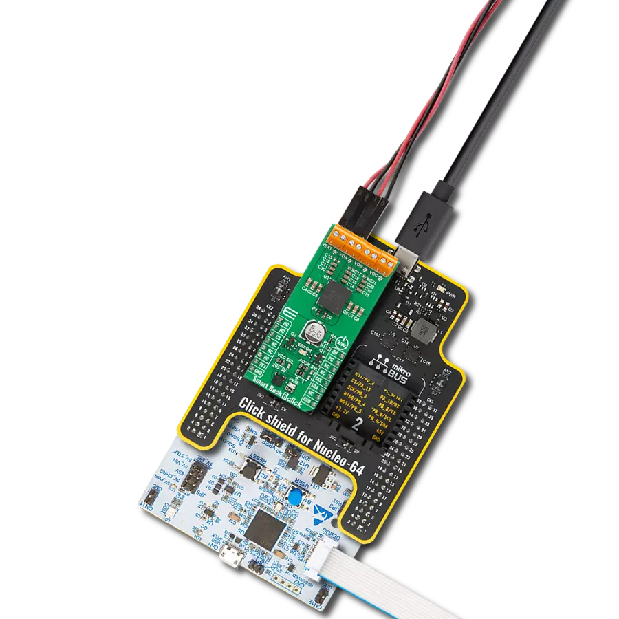
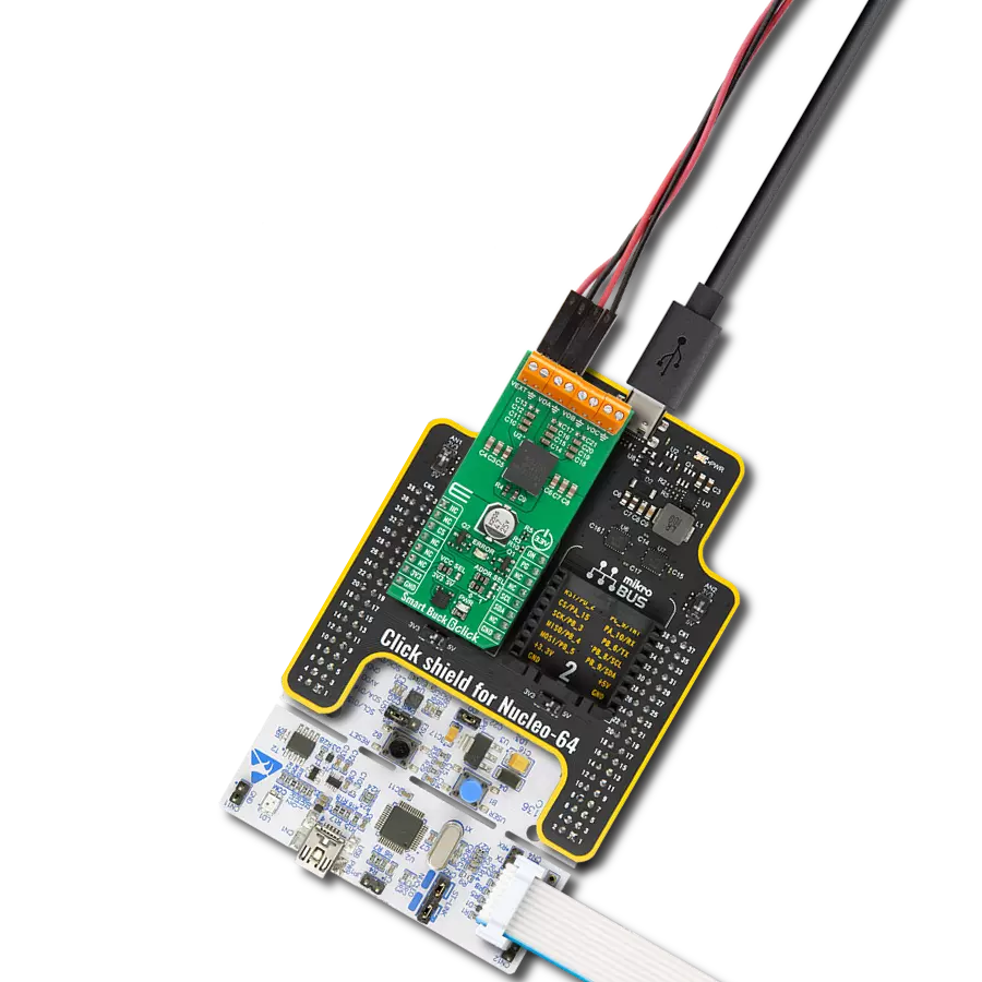
Click Shield for Nucleo-64 comes equipped with two proprietary mikroBUS™ sockets, allowing all the Click board™ devices to be interfaced with the STM32 Nucleo-64 board with no effort. This way, Mikroe allows its users to add any functionality from our ever-growing range of Click boards™, such as WiFi, GSM, GPS, Bluetooth, ZigBee, environmental sensors, LEDs, speech recognition, motor control, movement sensors, and many more. More than 1537 Click boards™, which can be stacked and integrated, are at your disposal. The STM32 Nucleo-64 boards are based on the microcontrollers in 64-pin packages, a 32-bit MCU with an ARM Cortex M4 processor operating at 84MHz, 512Kb Flash, and 96KB SRAM, divided into two regions where the top section represents the ST-Link/V2 debugger and programmer while the bottom section of the board is an actual development board. These boards are controlled and powered conveniently through a USB connection to program and efficiently debug the Nucleo-64 board out of the box, with an additional USB cable connected to the USB mini port on the board. Most of the STM32 microcontroller pins are brought to the IO pins on the left and right edge of the board, which are then connected to two existing mikroBUS™ sockets. This Click Shield also has several switches that perform functions such as selecting the logic levels of analog signals on mikroBUS™ sockets and selecting logic voltage levels of the mikroBUS™ sockets themselves. Besides, the user is offered the possibility of using any Click board™ with the help of existing bidirectional level-shifting voltage translators, regardless of whether the Click board™ operates at a 3.3V or 5V logic voltage level. Once you connect the STM32 Nucleo-64 board with our Click Shield for Nucleo-64, you can access hundreds of Click boards™, working with 3.3V or 5V logic voltage levels.

Used MCU Pins
mikroBUS™ mapper
Take a closer look
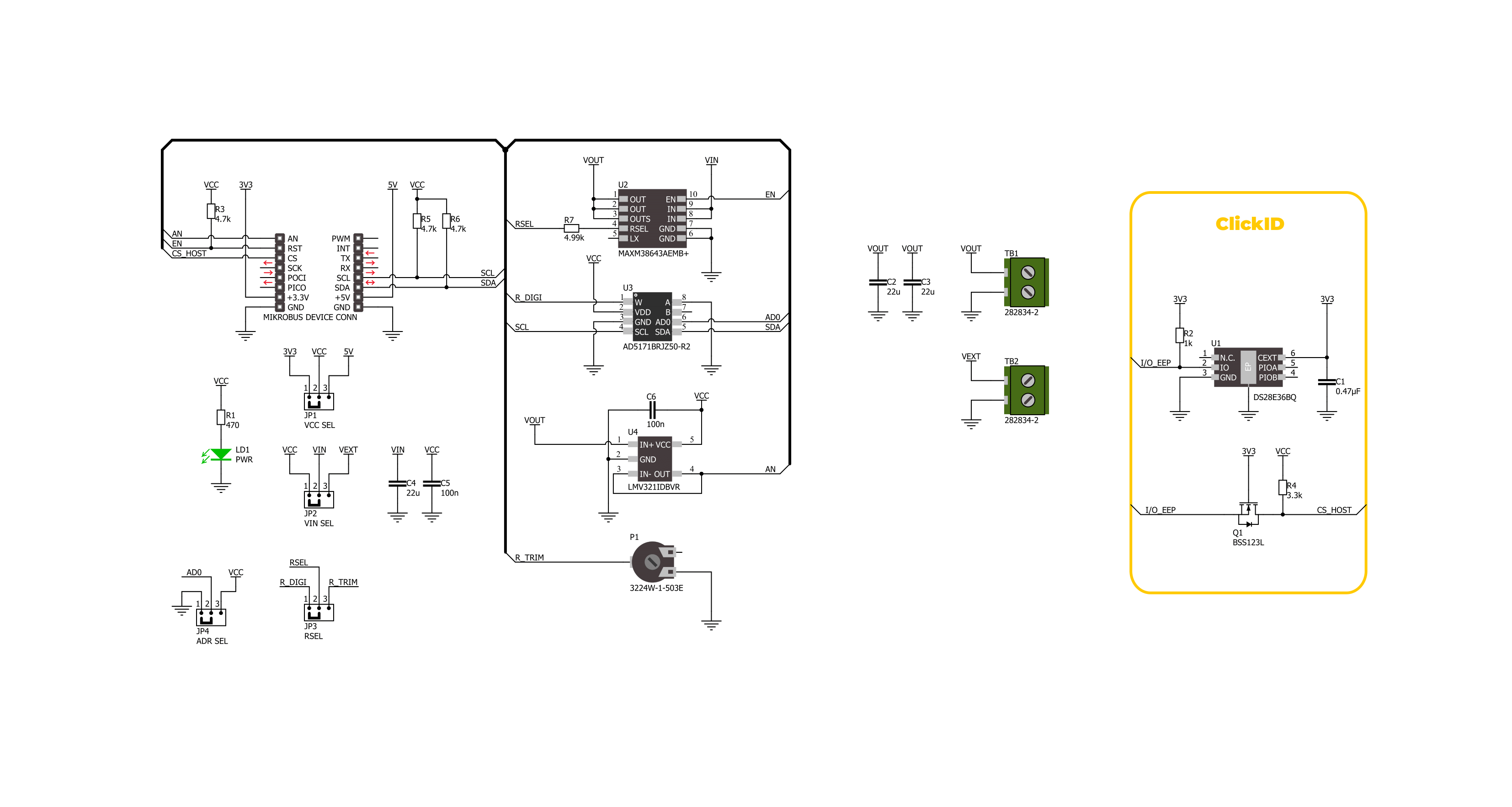
Click board™ Schematic
Step by step
Project assembly
Start by selecting your development board and Click board™. Begin with the Nucleo 64 with STM32F446RE MCU as your development board.


Software Support
Library Description
This library contains API for Buck 18 Click driver.
Key functions:
buck18_set_vout- This function sets the voltage output level.buck18_read_voltage- This function reads raw ADC value and converts it to proportional voltage level.buck18_enable- This function turns on the power switch and enables the buck mode.
Open Source
Code example
The complete application code and a ready-to-use project are available through the NECTO Studio Package Manager for direct installation in the NECTO Studio. The application code can also be found on the MIKROE GitHub account.
/*!
 * @file main.c
 * @brief Buck 18 Click Example.
 *
 * # Description
 * This example demonstrates the use of the Buck 18 Click board by changing the output voltage.
 *
 * The demo application is composed of two sections :
 *
 * ## Application Init
 * Initialization of I2C module and log UART.
 * After driver initialization, the app executes a default configuration.
 *
 * ## Application Task
 * The demo application changes the output voltage and displays the current voltage output value.
 * Results are being sent to the UART Terminal, where you can track their changes.
 *
 * @author Nenad Filipovic
 *
 */

#include "board.h"
#include "log.h"
#include "buck18.h"

static buck18_t buck18;   /**< Buck 18 Click driver object. */
static log_t logger;    /**< Logger object. */

void application_init ( void )
{
    log_cfg_t log_cfg;  /**< Logger config object. */
    buck18_cfg_t buck18_cfg;  /**< Click config object. */

    /**
     * Logger initialization.
     * Default baud rate: 115200
     * Default log level: LOG_LEVEL_DEBUG
     * @note If USB_UART_RX and USB_UART_TX
     * are defined as HAL_PIN_NC, you will
     * need to define them manually for log to work.
     * See @b LOG_MAP_USB_UART macro definition for detailed explanation.
     */
    LOG_MAP_USB_UART( log_cfg );
    log_init( &logger, &log_cfg );
    log_info( &logger, " Application Init " );

    // Click initialization.
    buck18_cfg_setup( &buck18_cfg );
    BUCK18_MAP_MIKROBUS( buck18_cfg, MIKROBUS_1 );
    err_t init_flag = buck18_init( &buck18, &buck18_cfg );
    if ( ( ADC_ERROR == init_flag ) || ( I2C_MASTER_ERROR == init_flag ) )
    {
        log_error( &logger, " Communication init." );
        for ( ; ; );
    }

    if ( BUCK18_ERROR == buck18_default_cfg ( &buck18 ) )
    {
        log_error( &logger, " Default configuration." );
        for ( ; ; );
    }

    log_info( &logger, " Application Task " );
}

void application_task ( void )
{
    for ( buck18_vout_t vout = BUCK18_VOUT_3V3; vout <= BUCK18_VOUT_0V9; vout++ )
    {
        if ( BUCK18_OK == buck18_set_vout( &buck18, vout ) )
        {
            float voltage = 0;
            if ( BUCK18_OK == buck18_read_voltage( &buck18, &voltage ) )
            {
                log_printf( &logger, " Voltage : %.3f[V]\r\n\n", voltage );
                Delay_ms ( 1000 );
                Delay_ms ( 1000 );
                Delay_ms ( 1000 );
                Delay_ms ( 1000 );
                Delay_ms ( 1000 );
            }
        }
    }
}

int main ( void )
{
    /* Do not remove this line or clock might not be set correctly. */
    #ifdef PREINIT_SUPPORTED
    preinit();
    #endif

    application_init( );

    for ( ; ; )
    {
        application_task( );
    }

    return 0;
}

// ------------------------------------------------------------------------ END
Additional Support
Resources
Category:Buck