Explore the newest pressure data with BMP388 and STM32F091RC
The future of pressure measurement
Published Feb 26, 2024
Click board™
Pressure 5 Click
Dev. board
Nucleo-64 with STM32F091RC MCU
Compiler
NECTO Studio
MCU
STM32F091RC
With our digital sensors, you can monitor and control pressure variations in real time, ensuring safety and precision in your applications
A
A
Hardware Overview
How does it work?
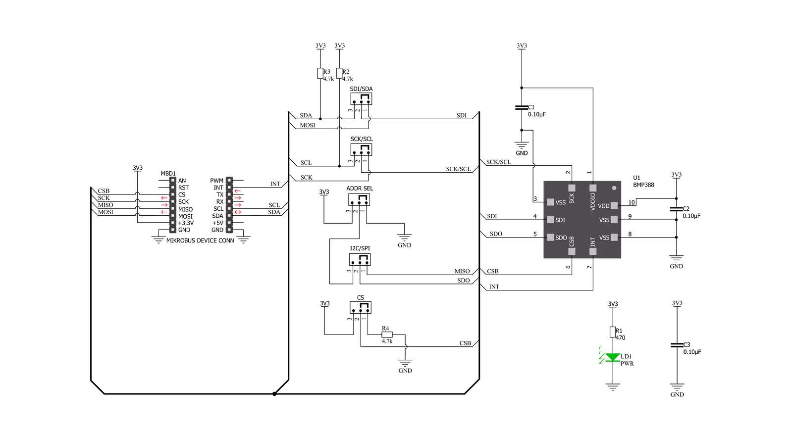
Pressure 5 Click is based on the BMP388, a digital pressure sensor, from Bosch Sensortec. This sensor consists of a piezo-resistive pressure sensing element and a mixed-signal ASIC which performs A/D conversions and provides the conversion results through a digital interface. This advanced MEMS technology offers a high measurement precision of 0.08hPa, as well as low TOC (thermal coefficient) of only 0.75 Pa/K. The sensor is enclosed in a small metal lid housing and is highly resilient: it can operate in a range of 300 hPa to 1250 hPa but can withstand up to 20,000 hPa before the membrane breaks down. The BMP388 offers a set of pressure and temperature measurement options. It can be programmed to skip either thermal or pressure measurement, allowing faster measurement of the required property. The low TOC of only 0.75Pa/K allows reading of the pressure with very small drift over temperature. Resolution of 0.08hPa allows calculating of the altitude with the accuracy of about 66 cm, which is ideal for indoor navigation applications (drones, flying toy models, and similar). The IIR filter is especially useful for indoor usage, allowing filtering of some short-term disturbances, such as slamming doors or windows. FIFO buffer allows for an optimization of the host firmware, reducing the data traffic through the
communication interface. It has 512 bytes and it is backed up by an interrupt engine, which can trigger an interrupt event when the buffer is full, or when the watermark level is reached. Also, the behavior of the FIFO buffer can be programmed to either skip new data once it is full or to overwrite the oldest data. The interrupt is available over the INT pin, and can be used to further optimize the host firmware (i.e. to reduce the power consumption by utilizing the INT pin to wake up the host MCU). Besides FIFO events, the INT pin also signals when there is a new data available at the output register (Data Ready event). This sensor consists of a mixed signal front-end (ASIC) and a piezo-sensitive pressure sensing element. The ASIC contains a low-noise 24-bit A/D converter, along with the digital signal processing section. The measurement data is available either over the I2C or the SPI interface. Pressure 5 click offers a choice between these two interfaces. The selection can be done by positioning SMD jumpers labeled as COMM SEL to an appropriate position. Note that all the jumpers must be placed to the same side, else the Click board™ may become unresponsive. While the I2C interface is selected, the BMP388 allows the choice of the least significant bit (LSB) of its I2C slave address. This can be done by using the SMD jumper
labeled as ADDR SEL. The overall power consumption depends on several factors, such as the oversampling value, measurement rate, power mode, standby duration, and so on. Bosh Sensortech recommends a set of operational parameters for different applications, in the form of a table, in the BMP388 datasheet. In general, this sensor allows several power modes, regardless of the selected measurement parameters. When the measurement is completed, raw ADC values will be available in the output registers. However, to obtain actual pressure and temperature readings, a compensation algorithm needs to be applied. A set of compensation parameters is available in the non-volatile memory of the BMP388 device. These compensation parameters take into account slight differences between the produced samples and each BMP388 device has its own set of parameters. The BMP388 datasheet offers detailed instructions on how to apply these compensating algorithms properly. However, MikroElektronika provides a library with functions which can be used for a simplified and thus faster application development. The library also contains a demo example, which demonstrates the use of these functions. The demo application can be used as a reference for a custom design.


Features overview
Development board
Nucleo-64 with STM32F091RC MCU offers a cost-effective and adaptable platform for developers to explore new ideas and prototype their designs. This board harnesses the versatility of the STM32 microcontroller, enabling users to select the optimal balance of performance and power consumption for their projects. It accommodates the STM32 microcontroller in the LQFP64 package and includes essential components such as a user LED, which doubles as an ARDUINO® signal, alongside user and reset push-buttons, and a 32.768kHz crystal oscillator for precise timing operations. Designed with expansion and flexibility in mind, the Nucleo-64 board features an ARDUINO® Uno V3 expansion connector and ST morpho extension pin
headers, granting complete access to the STM32's I/Os for comprehensive project integration. Power supply options are adaptable, supporting ST-LINK USB VBUS or external power sources, ensuring adaptability in various development environments. The board also has an on-board ST-LINK debugger/programmer with USB re-enumeration capability, simplifying the programming and debugging process. Moreover, the board is designed to simplify advanced development with its external SMPS for efficient Vcore logic supply, support for USB Device full speed or USB SNK/UFP full speed, and built-in cryptographic features, enhancing both the power efficiency and security of projects. Additional connectivity is
provided through dedicated connectors for external SMPS experimentation, a USB connector for the ST-LINK, and a MIPI® debug connector, expanding the possibilities for hardware interfacing and experimentation. Developers will find extensive support through comprehensive free software libraries and examples, courtesy of the STM32Cube MCU Package. This, combined with compatibility with a wide array of Integrated Development Environments (IDEs), including IAR Embedded Workbench®, MDK-ARM, and STM32CubeIDE, ensures a smooth and efficient development experience, allowing users to fully leverage the capabilities of the Nucleo-64 board in their projects.

Microcontroller Overview
MCU Card / MCU

Architecture
ARM Cortex-M0
MCU Memory (KB)
256
Silicon Vendor
STMicroelectronics
Pin count
64
RAM (Bytes)
32768
You complete me!
Accessories
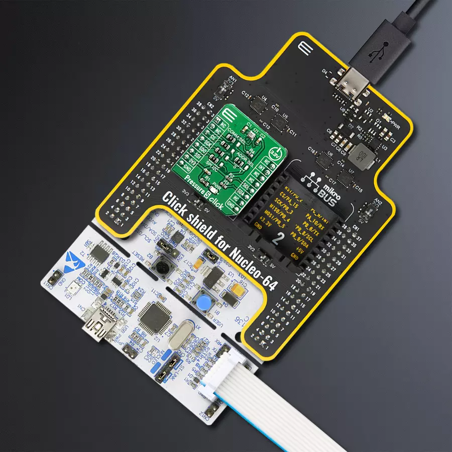
Click Shield for Nucleo-64 comes equipped with two proprietary mikroBUS™ sockets, allowing all the Click board™ devices to be interfaced with the STM32 Nucleo-64 board with no effort. This way, Mikroe allows its users to add any functionality from our ever-growing range of Click boards™, such as WiFi, GSM, GPS, Bluetooth, ZigBee, environmental sensors, LEDs, speech recognition, motor control, movement sensors, and many more. More than 1537 Click boards™, which can be stacked and integrated, are at your disposal. The STM32 Nucleo-64 boards are based on the microcontrollers in 64-pin packages, a 32-bit MCU with an ARM Cortex M4 processor operating at 84MHz, 512Kb Flash, and 96KB SRAM, divided into two regions where the top section represents the ST-Link/V2 debugger and programmer while the bottom section of the board is an actual development board. These boards are controlled and powered conveniently through a USB connection to program and efficiently debug the Nucleo-64 board out of the box, with an additional USB cable connected to the USB mini port on the board. Most of the STM32 microcontroller pins are brought to the IO pins on the left and right edge of the board, which are then connected to two existing mikroBUS™ sockets. This Click Shield also has several switches that perform functions such as selecting the logic levels of analog signals on mikroBUS™ sockets and selecting logic voltage levels of the mikroBUS™ sockets themselves. Besides, the user is offered the possibility of using any Click board™ with the help of existing bidirectional level-shifting voltage translators, regardless of whether the Click board™ operates at a 3.3V or 5V logic voltage level. Once you connect the STM32 Nucleo-64 board with our Click Shield for Nucleo-64, you can access hundreds of Click boards™, working with 3.3V or 5V logic voltage levels.

Used MCU Pins
mikroBUS™ mapper
Take a closer look
Click board™ Schematic
Step by step
Project assembly
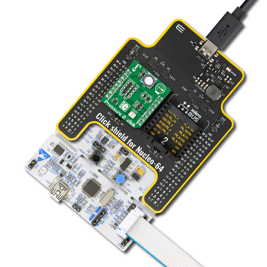
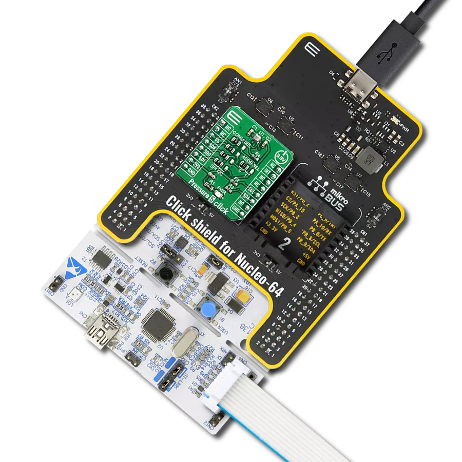
Start by selecting your development board and Click board™. Begin with the Nucleo-64 with STM32F091RC MCU as your development board.


Track your results in real time
Application Output
1. Application Output - In Debug mode, the 'Application Output' window enables real-time data monitoring, offering direct insight into execution results. Ensure proper data display by configuring the environment correctly using the provided tutorial.

2. UART Terminal - Use the UART Terminal to monitor data transmission via a USB to UART converter, allowing direct communication between the Click board™ and your development system. Configure the baud rate and other serial settings according to your project's requirements to ensure proper functionality. For step-by-step setup instructions, refer to the provided tutorial.

3. Plot Output - The Plot feature offers a powerful way to visualize real-time sensor data, enabling trend analysis, debugging, and comparison of multiple data points. To set it up correctly, follow the provided tutorial, which includes a step-by-step example of using the Plot feature to display Click board™ readings. To use the Plot feature in your code, use the function: plot(*insert_graph_name*, variable_name);. This is a general format, and it is up to the user to replace 'insert_graph_name' with the actual graph name and 'variable_name' with the parameter to be displayed.

Software Support
Library Description
This library contains API for Pressure 5 Click driver.
Key functions:
pressure5_update_coefficient- This function allows you to update the calibration coefficientpressure5_get_temperature_data- This function gets temperature in Celsiuspressure5_get_pressure_data- This function gets pressure in mBar
Open Source
Code example
The complete application code and a ready-to-use project are available through the NECTO Studio Package Manager for direct installation in the NECTO Studio. The application code can also be found on the MIKROE GitHub account.
/*!
 * \file
 * \brief Pressure5 Click example
 *
 * # Description
 * This example preforms Temperature and Pressure measurement.
 *
 * The demo application is composed of two sections :
 *
 * ## Application Init
 * Initialization driver init, test comunication, software reset, update
 * coefficient and configuration module for start measurement.
 *
 * ## Application Task
 * Reads Pressure data in [mBar] and Temperature data in [C].
 * Logs all data to the USBUART every 2 seconds.
 *
 * \author MikroE Team
 *
 */
// ------------------------------------------------------------------- INCLUDES

#include "board.h"
#include "log.h"
#include "pressure5.h"

// ------------------------------------------------------------------ VARIABLES

static pressure5_t pressure5;
static log_t logger;

static float temperature;
static float pressure;

// ------------------------------------------------------ APPLICATION FUNCTIONS

void application_init ( void )
{
    log_cfg_t log_cfg;
    pressure5_cfg_t cfg;
    PRESSURE5_RETVAL init_ret;

    /**
     * Logger initialization.
     * Default baud rate: 115200
     * Default log level: LOG_LEVEL_DEBUG
     * @note If USB_UART_RX and USB_UART_TX
     * are defined as HAL_PIN_NC, you will
     * need to define them manually for log to work.
     * See @b LOG_MAP_USB_UART macro definition for detailed explanation.
     */
    LOG_MAP_USB_UART( log_cfg );
    log_init( &logger, &log_cfg );
    log_info( &logger, "---- Application Init ----" );

    //  Click initialization.

    pressure5_cfg_setup( &cfg );
    PRESSURE5_MAP_MIKROBUS( cfg, MIKROBUS_1 );
    pressure5_init( &pressure5, &cfg );
    pressure5_default_cfg( &pressure5 );
}

void application_task ( void )
{
    //  Task implementation.

    temperature = pressure5_get_temperature_data ( &pressure5 );
    log_printf( &logger, "Temperature: %.2f C\r\n", temperature );

    pressure = pressure5_get_pressure_data ( &pressure5 );
    log_printf( &logger, "Pressure: %.2f mBar\r\n ", pressure );
    log_printf( &logger, "\r\n" );

    Delay_ms ( 1000 );
}

int main ( void )
{
    /* Do not remove this line or clock might not be set correctly. */
    #ifdef PREINIT_SUPPORTED
    preinit();
    #endif

    application_init( );

    for ( ; ; )
    {
        application_task( );
    }

    return 0;
}


// ------------------------------------------------------------------------ END