Provide a pulse train or a square wave proportional to ambient light intensity with TSL230BR and STM32F091RC
Programmable light-to-frequency converter

Published Mar 09, 2024
Click board™
LightHz Click
Dev. board
Nucleo-64 with STM32F091RC MCU
Compiler
NECTO Studio
MCU
STM32F091RC
Achieve an accurate, high-resolution light intensity measurement in various applications, from basic ambient light sensing to rough color detection
A
A
Hardware Overview
How does it work?
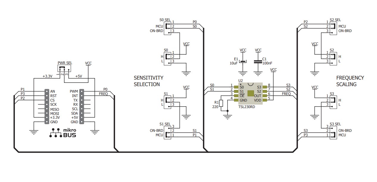
LightHz Click is based on the TSL230BR, a programmable light-to-frequency converter from ams OSRAM. It combines a configurable silicon photodiode and a current-to-frequency converter and has a high-resolution conversion of light intensity with no external components. The sensor responds over the 320nm to 1050nm light range and is temperature-compensated for the ultraviolet-to-visible light range of 320nm to 700nm. Device sensitivity is selectable in three ranges, providing two decades of adjustment, while the full-scale output frequency can be scaled by one of four preset values with 5% absolute tolerance. The LightHz Click uses its frequency output to communicate with the host MCU over the OUT pin of the mikroBUS™ socket. The board comes with four SMD jumpers labeled MCU ON-BRD, which allows you to choose the scaling and sensitivity configuration to be controlled by the host MCU
rather than the onboard jumper selection. The latter is set by default. Using default MCU ON-BRD selection, the sensitivity is controlled by two logic inputs on S0 and S1 on the jumper labeled SENSITIVITY SELECTION. You can choose between 1x, 10, 100x, and power-down options by combining four available positions. The sensitivity of this sensor is adjusted using an electronic iris technique, similar to an aperture control. This way, it is possible to change the device's response to a given amount of light, which allows the device to be optimized to a given light level while preserving the output frequency range. The 100x option is set by default. Using default MCU ON-BRD selection, the output frequency scaling is controlled by two logic inputs on S2 and S3 on the jumper labeled FREQUENCY SCALING. By a combination of four available positions, you can choose between 1, 2, 10, and 100 dividing values. The value 1 means no
division as a direct output and is a fixed-pulse-width pulse train. The higher divider means lower frequency ranges for high-resolution measurement; the 100 value is set by default. If your choice is to control the sensor by the host MCU by selecting the MCU ON-BRD jumpers to MCU, then the logic inputs for scaling and selection become available on the S0, S1, S2, and S3 pins of the mikroBUS™ socket. The combination tables are in our documentation section below. This Click board™ can operate with either 3.3V or 5V logic voltage levels selected via the PWR SEL jumper. This way, both 3.3V and 5V capable MCUs can use the communication lines properly. However, the Click board™ comes equipped with a library containing easy-to-use functions and an example code that can be used as a reference for further development.

Features overview
Development board
Nucleo-64 with STM32F091RC MCU offers a cost-effective and adaptable platform for developers to explore new ideas and prototype their designs. This board harnesses the versatility of the STM32 microcontroller, enabling users to select the optimal balance of performance and power consumption for their projects. It accommodates the STM32 microcontroller in the LQFP64 package and includes essential components such as a user LED, which doubles as an ARDUINO® signal, alongside user and reset push-buttons, and a 32.768kHz crystal oscillator for precise timing operations. Designed with expansion and flexibility in mind, the Nucleo-64 board features an ARDUINO® Uno V3 expansion connector and ST morpho extension pin
headers, granting complete access to the STM32's I/Os for comprehensive project integration. Power supply options are adaptable, supporting ST-LINK USB VBUS or external power sources, ensuring adaptability in various development environments. The board also has an on-board ST-LINK debugger/programmer with USB re-enumeration capability, simplifying the programming and debugging process. Moreover, the board is designed to simplify advanced development with its external SMPS for efficient Vcore logic supply, support for USB Device full speed or USB SNK/UFP full speed, and built-in cryptographic features, enhancing both the power efficiency and security of projects. Additional connectivity is
provided through dedicated connectors for external SMPS experimentation, a USB connector for the ST-LINK, and a MIPI® debug connector, expanding the possibilities for hardware interfacing and experimentation. Developers will find extensive support through comprehensive free software libraries and examples, courtesy of the STM32Cube MCU Package. This, combined with compatibility with a wide array of Integrated Development Environments (IDEs), including IAR Embedded Workbench®, MDK-ARM, and STM32CubeIDE, ensures a smooth and efficient development experience, allowing users to fully leverage the capabilities of the Nucleo-64 board in their projects.

Microcontroller Overview
MCU Card / MCU

Architecture
ARM Cortex-M0
MCU Memory (KB)
256
Silicon Vendor
STMicroelectronics
Pin count
64
RAM (Bytes)
32768
You complete me!
Accessories
Click Shield for Nucleo-64 comes equipped with two proprietary mikroBUS™ sockets, allowing all the Click board™ devices to be interfaced with the STM32 Nucleo-64 board with no effort. This way, Mikroe allows its users to add any functionality from our ever-growing range of Click boards™, such as WiFi, GSM, GPS, Bluetooth, ZigBee, environmental sensors, LEDs, speech recognition, motor control, movement sensors, and many more. More than 1537 Click boards™, which can be stacked and integrated, are at your disposal. The STM32 Nucleo-64 boards are based on the microcontrollers in 64-pin packages, a 32-bit MCU with an ARM Cortex M4 processor operating at 84MHz, 512Kb Flash, and 96KB SRAM, divided into two regions where the top section represents the ST-Link/V2 debugger and programmer while the bottom section of the board is an actual development board. These boards are controlled and powered conveniently through a USB connection to program and efficiently debug the Nucleo-64 board out of the box, with an additional USB cable connected to the USB mini port on the board. Most of the STM32 microcontroller pins are brought to the IO pins on the left and right edge of the board, which are then connected to two existing mikroBUS™ sockets. This Click Shield also has several switches that perform functions such as selecting the logic levels of analog signals on mikroBUS™ sockets and selecting logic voltage levels of the mikroBUS™ sockets themselves. Besides, the user is offered the possibility of using any Click board™ with the help of existing bidirectional level-shifting voltage translators, regardless of whether the Click board™ operates at a 3.3V or 5V logic voltage level. Once you connect the STM32 Nucleo-64 board with our Click Shield for Nucleo-64, you can access hundreds of Click boards™, working with 3.3V or 5V logic voltage levels.

Used MCU Pins
mikroBUS™ mapper
Take a closer look
Click board™ Schematic
Step by step
Project assembly
Start by selecting your development board and Click board™. Begin with the Nucleo-64 with STM32F091RC MCU as your development board.


Software Support
Library Description
This library contains API for LightHz Click driver.
Key functions:
lighthz_set_sensitivity- This function sets the sensor sensitivitylighthz_set_frequency_scaling- This function sets the sensor frequency scalinglighthz_get_freq_pin- This function returns the freq pin logic state
Open Source
Code example
The complete application code and a ready-to-use project are available through the NECTO Studio Package Manager for direct installation in the NECTO Studio. The application code can also be found on the MIKROE GitHub account.
/*!
 * @file main.c
 * @brief LightHz Click Example.
 *
 * # Description
 * This example demonstrates the use of LightHz Click board by measuring and displaying
 * the frequency of clock output signal. The higher the light intensity the higher the frequency.
 *
 * The demo application is composed of two sections :
 *
 * ## Application Init
 * Initializes the driver and sets the sensitivity mode and frequency scaling in case
 * the onboard jumpers are set to MCU instead to ON-BRD.
 *
 * ## Application Task
 * Measures the clock output frequency using the polling method and delays. The results are being
 * sent to the USB UART.
 *
 * @author Stefan Filipovic
 *
 */

#include "board.h"
#include "log.h"
#include "lighthz.h"

static lighthz_t lighthz;   /**< LightHz Click driver object. */
static log_t logger;        /**< Logger object. */

void application_init ( void )
{
    log_cfg_t log_cfg;  /**< Logger config object. */
    lighthz_cfg_t lighthz_cfg;  /**< Click config object. */

    /**
     * Logger initialization.
     * Default baud rate: 115200
     * Default log level: LOG_LEVEL_DEBUG
     * @note If USB_UART_RX and USB_UART_TX
     * are defined as HAL_PIN_NC, you will
     * need to define them manually for log to work.
     * See @b LOG_MAP_USB_UART macro definition for detailed explanation.
     */
    LOG_MAP_USB_UART( log_cfg );
    log_init( &logger, &log_cfg );
    log_info( &logger, " Application Init " );

    // Click initialization.
    lighthz_cfg_setup( &lighthz_cfg );
    LIGHTHZ_MAP_MIKROBUS( lighthz_cfg, MIKROBUS_1 );
    if ( DIGITAL_OUT_UNSUPPORTED_PIN == lighthz_init( &lighthz, &lighthz_cfg ) )
    {
        log_error( &logger, " Communication init." );
        for ( ; ; );
    }

    lighthz_set_sensitivity ( &lighthz, LIGHTHZ_SENS_100X );
    lighthz_set_frequency_scaling ( &lighthz, LIGHTHZ_FSCALE_100 );

    log_info( &logger, " Application Task " );
}

void application_task ( void )
{
    uint32_t freq_cnt = 0;
    uint16_t sample_cnt = 0;

    // Wait for the clock rising edge signal
    while ( !hal_ll_gpio_read_pin_input( &lighthz.freq.pin ) );

    // A loop for measuring the clock frequency counts. It's not an ideal implementation.
    // Here we should use an external interrupt on the clock pin rising edge and a timer interrupt
    // for the best accuracy, however, those interrupt features have not yet been implemented in the SDK.
    while ( ( sample_cnt < LIGHTHZ_SAMPLE_COUNTS ) && ( freq_cnt < LIGHTHZ_MAX_COUNTS_PER_S ) )
    {
        // A single iteration in the loops below should take as close to 10us as possible
        // So to improve the measurement accuracy adjust the delay below for your system
        while ( hal_ll_gpio_read_pin_input( &lighthz.freq.pin ) )
        {
            freq_cnt++;
            Delay_us ( LIGHTHZ_DELAY_US );
        }
        while ( !hal_ll_gpio_read_pin_input( &lighthz.freq.pin ) )
        {
            freq_cnt++;
            Delay_us ( LIGHTHZ_DELAY_US );
        }
        sample_cnt++;
    }
    freq_cnt /= sample_cnt;

    // The higher the light intensity the higher the frequency.
    log_printf( &logger, " Frequency: %.1f Hz\r\n\n", ( float ) LIGHTHZ_MAX_COUNTS_PER_S / freq_cnt );

    Delay_ms ( 1000 );
}

int main ( void )
{
    /* Do not remove this line or clock might not be set correctly. */
    #ifdef PREINIT_SUPPORTED
    preinit();
    #endif

    application_init( );

    for ( ; ; )
    {
        application_task( );
    }

    return 0;
}

// ------------------------------------------------------------------------ END
Additional Support
Resources
Category:Optical


